Products
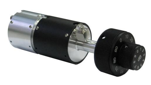
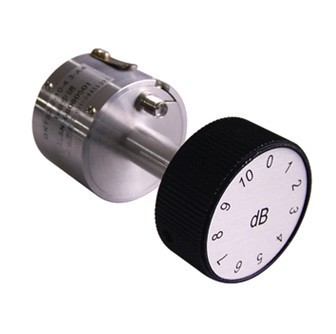
0.1-40Ghz digital Attenuator Programmed Attenuator
| Leader-mw | Introduction 0.1-40Ghz Digital Attenuator Programmed Attenuator |
The 0.1-40GHz Digital Attenuator is a highly sophisticated and programmable device designed to precisely control the amplitude of high-frequency signals within the specified range. This versatile tool is an essential component in various fields, including telecommunications, research laboratories, and electronic warfare systems, where signal strength adjustment is critical for optimal performance and testing accuracy.
Key Features:
1. **Broad Frequency Range**: Covering from 0.1 to 40 GHz, this attenuator caters to a wide spectrum of applications, making it suitable for both microwave and millimeter-wave frequencies. This extensive range enables its use in diverse scenarios, from basic RF testing to advanced satellite communication systems.
2. **Programmable Attenuation**: Unlike traditional fixed attenuators, this digital version allows users to set specific attenuation levels through programming interfaces, typically via USB, LAN, or GPIB connections. The ability to adjust the attenuation dynamically enhances flexibility in experiment design and system optimization.
3. **High Precision & Resolution**: With attenuation steps as fine as 0.1 dB, users can achieve precise control over signal strength, crucial for accurate measurements and minimizing signal distortion. This level of precision ensures reliable performance even in the most demanding applications.
4. **Low Insertion Loss & High Linearity**: Designed with minimal insertion loss and excellent linearity across its operating range, the attenuator maintains signal integrity while providing the necessary reduction in power. This feature is vital for preserving the quality of the signal during transmission or measurement processes.
5. **Remote Control & Automation Compatibility**: The inclusion of standardized communication protocols facilitates integration into automated test setups and remote control systems. This capability streamlines operations, reduces human error, and accelerates testing procedures in production environments.
6. **Robust Construction & Reliability**: Built to withstand rigorous use, the attenuator features a durable design that ensures consistent performance under extreme temperatures, vibrations, and other challenging conditions. Its reliability makes it ideal for long-term deployment in harsh industrial or outdoor environments.
In summary, the 0.1-40GHz Digital Attenuator stands out as a powerful and adaptable solution for managing high-frequency signal strength with unparalleled precision and control. Its broadband coverage, programmable nature, and robust build make it an invaluable asset for professionals seeking to enhance their signal processing capabilities across a multitude of high-tech domains.
| Leader-mw | Specification |
|
Model No. |
Freq.Range |
Min. |
Typ. |
Max. |
| LKTSJ-0.1/40-0.5S | 0.1-40 GHz |
0.5dB Step |
31.5 dB |
|
| Attenuation Accuracy | 0.5-15 dB |
±1.2 dB |
||
| 15-31.5 dB |
±2.0 dB |
|||
| Attenuation Flatness | 0.5-15 dB |
±1.2 dB |
||
| 15-31.5 dB |
±2.0 dB |
|||
| Insertion Loss |
6.5 dB |
7.0 dB |
||
| Input Power |
25 dBm |
28 dBm |
||
| VSWR |
1.6 |
2.0 |
||
| Control Voltage |
+3.3V/-3.3V |
|||
| Bias Voltage |
+3.5V/-3.5V |
|||
| Current |
20 mA |
|||
| Logic Input |
“1”= on; “0”= off |
|||
| Logic“0” |
0 |
0.8V |
||
| Logic“1” |
+1.2V |
+3.3V |
||
| Impedance | 50 Ω | |||
| RF Connector | 2.92-(f) | |||
| Input Control Connector | 15 Pin Female | |||
| Weight | 25 g | |||
| Operation Temperature | -45℃ ~ +85 ℃ | |||
| Leader-mw | Environmental Specifications |
| Operational Temperature | -30ºC~+60ºC |
| Storage Temperature | -50ºC~+85ºC |
| Vibration | 25gRMS (15 degrees 2KHz) endurance, 1 hour per axis |
| Humidity | 100% RH at 35ºc, 95%RH at 40ºc |
| Shock | 20G for 11msec half sine wave,3 axis both directions |
Outline Drawing:
All Dimensions in mm
Outline Tolerances ± 0.5(0.02)
Mounting Holes Tolerances ±0.2(0.008)
All Connectors: 2.92-Female

| Leader-mw | Attenuator accuracy |
| Leader-mw | Truth Table: |
|
Control Input TTL |
Signal Path State |
|||||
|
C6 |
C5 |
C4 |
C3 |
C2 |
C1 |
|
|
0 |
0 |
0 |
0 |
0 |
0 |
Reference IL |
|
0 |
0 |
0 |
0 |
0 |
1 |
0.5dB |
|
0 |
0 |
0 |
0 |
1 |
0 |
1dB |
|
0 |
0 |
0 |
1 |
0 |
0 |
2dB |
|
0 |
0 |
1 |
0 |
0 |
0 |
4dB |
|
0 |
1 |
0 |
0 |
0 |
0 |
8dB |
|
1 |
0 |
0 |
0 |
0 |
0 |
16dB |
|
1 |
1 |
1 |
1 |
1 |
1 |
31.5dB |
| Leader-mw | D-sub15 Definition |
|
1 |
+3.3V |
|
2 |
GND |
|
3 |
-3.3V |
|
4 |
C1 |
|
5 |
C2 |
|
6 |
C3 |
|
7 |
C4 |
|
8 |
C5 |
|
9 |
C6 |
|
10-15 |
NC |


