
Products


LDC-0.5/26.5-20S 0.5-26.5GHz 20dB Directional Coupler
| Leader-mw | Introduction to Broadband Couplers |
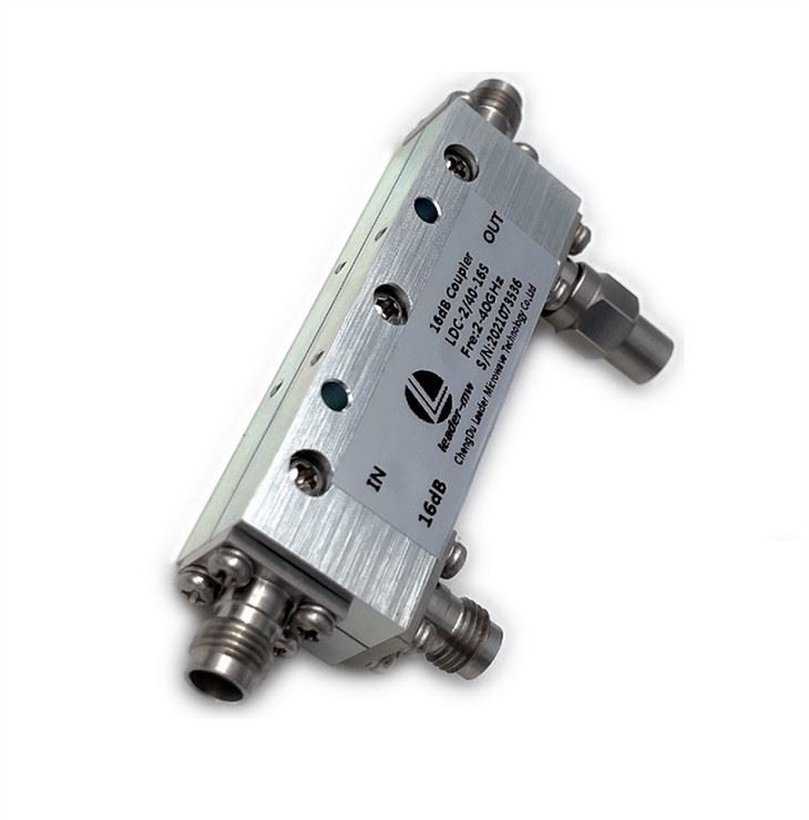
Introducing our latest innovation in RF technology - the 0.5-26.5GHz 20dB Directional Coupler. This cutting-edge device is designed to meet the demands of modern communication systems, offering exceptional performance and reliability across a wide frequency range.
The 20dB Directional Coupler is an essential component for signal monitoring, power measurements, and other RF applications. With its broad frequency coverage from 0.5GHz to 26.5GHz, this coupler is versatile and adaptable to various communication systems, making it an ideal choice for engineers and technicians working in the field of RF and microwave technology.
One of the key features of this directional coupler is its high coupling factor of 20dB, which ensures accurate and efficient signal monitoring without compromising signal integrity. This makes it an invaluable tool for measuring and analyzing RF signals in both laboratory and field environments.
The compact and robust design of the directional coupler ensures easy integration into existing systems, while its high-quality construction guarantees long-term reliability and performance. Whether used in test and measurement equipment, radar systems, or satellite communication systems, this directional coupler delivers consistent and precise results.
Furthermore, the 20dB Directional Coupler is engineered to meet the stringent requirements of modern communication standards, making it an indispensable tool for engineers and researchers working on next-generation wireless technologies.
In conclusion, the 0.5-26.5GHz 20dB Directional Coupler represents a significant advancement in RF technology, offering exceptional performance, reliability, and versatility across a wide frequency range. With its high coupling factor and robust design, this directional coupler is poised to meet the evolving needs of the RF and microwave industry, making it an indispensable tool for professionals working in this field.
| Leader-mw | Specification |
Type No:LDC-0.5/26.5-20s
| No. | Parameter | Minimum | Typical | Maximum | Units |
| 1 | Frequency range | 0.5 | 26.5 | GHz | |
| 2 | Nominal Coupling | 20 | dB | ||
| 3 | Coupling Accuracy | ±0.7 | dB | ||
| 4 | Coupling Sensitivity to Frequency | ±0.1 | dB | ||
| 5 | Insertion Loss | 1.4 | dB | ||
| 6 | Directivity | 12 | dB | ||
| 7 | VSWR | 1.4 | - | ||
| 8 | Power | 30 | W | ||
| 9 | Operating Temperature Range | -40 | +85 | ˚C | |
| 10 | Impedance | - | 50 | - | Ω |
Remarks:
1. Include Theoretical loss 0.044db 2.Power rating is for load vswr better than 1.20:1
| Leader-mw | Environmental Specifications |
| Operational Temperature | -30ºC~+60ºC |
| Storage Temperature | -50ºC~+85ºC |
| Vibration | 25gRMS (15 degrees 2KHz) endurance, 1 hour per axis |
| Humidity | 100% RH at 35ºc, 95%RH at 40ºc |
| Shock | 20G for 11msec half sine wave,3 axis both directions |
| Leader-mw | Mechanical Specifications |
| Housing | Aluminum |
| Connector | ternary alloy three-partalloy |
| Female Contact: | gold plated beryllium bronze |
| Rohs | compliant |
| Weight | 0.15kg |
Outline Drawing:
All Dimensions in mm
Outline Tolerances ± 0.5(0.02)
Mounting Holes Tolerances ±0.2(0.008)
All Connectors: SMA-Female

| Leader-mw | Test Data |