
Products


4×4 Butler Matrix LDC-0.5/7-180s-4X4
| Leader-mw | Introduction to 4×4 Butler Matrix LDC-0.5/7-180s-4X4 |
The 4×4 Butler Matrix LDC-0.5/7-180S is a sophisticated beamforming network widely used in antenna systems to achieve precise signal direction control. It leverages leader-mw’s high-performance 90-degree and 180-degree Hybrid Couplers, which are critical components ensuring exceptional phase accuracy, minimal amplitude imbalance, and outstanding stability and repeatability. These couplers are designed to split and combine signals with high fidelity, enabling the Butler Matrix to generate multiple beams with consistent performance across a wide frequency range.
The 4×4 configuration supports four input and four output ports, making it ideal for applications such as phased array antennas, wireless communication systems, and radar systems. Its ability to create orthogonal beams allows for enhanced signal coverage and interference reduction, improving overall system efficiency. The use of leader-mw’s hybrid couplers ensures that the matrix maintains low insertion loss and high isolation, which are essential for maintaining signal integrity in complex multi-beam environments.
With its robust design and superior performance, the 4×4 Butler Matrix LDC-0.5/7-180S is a reliable solution for advanced RF and microwave systems, offering scalability and adaptability for modern communication technologies. Its combination of precision, stability, and repeatability makes it a preferred choice for engineers seeking high-performance beamforming solutions.
| Leader-mw | Specification |
Type No: 4×4 Butler Matrix LDC-0.5/7-180s-4X4
| No. | Parameter | Minimum | Typical | Maximum | Units |
| 1 | Frequency range |
0.5 |
- |
7 |
GHz |
| 2 | Insertion Loss |
- |
- |
11 |
dB |
| 3 | Phase Balance: |
- |
- |
±12 |
dB |
| 4 | Amplitude Balance |
- |
- |
±1.0 |
dB |
| 5 | Isolation |
14 |
- |
|
dB |
| 6 | VSWR |
- |
- |
1.5 |
- |
| 7 | Power |
|
|
20 |
W cw |
| 8 | Operating Temperature Range |
-40 |
- |
+85 |
˚C |
| 9 | Impedance |
- |
50 |
- |
Ω |
| 10 | Connecter |
Sma-f |
|
|
|
| 11 | Preferred finish |
Black/yellow/green/sliver/blue |
|||
Remarks:
1.Insertion loss Include Theoretical loss 6db 2.Power rating is for load vswr better than 1.20:1
| Leader-mw | Environmental Specifications |
| Operational Temperature | -30ºC~+60ºC |
| Storage Temperature | -50ºC~+85ºC |
| Vibration | 25gRMS (15 degrees 2KHz) endurance, 1 hour per axis |
| Humidity | 100% RH at 35ºc, 95%RH at 40ºc |
| Shock | 20G for 11msec half sine wave,3 axis both directions |
| Leader-mw | Mechanical Specifications |
| Housing | Aluminum |
| Connector | ternary alloy three-partalloy |
| Female Contact: | gold plated beryllium bronze |
| Rohs | compliant |
| Weight | 0.6kg |
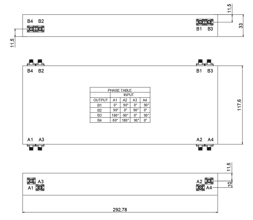
Outline Drawing:
All Dimensions in mm
Outline Tolerances ± 0.5(0.02)
Mounting Holes Tolerances ±0.2(0.008)
All Connectors:SMA-Female
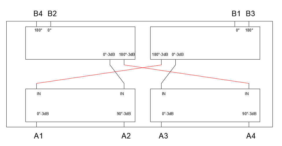
| Leader-mw | Schematic diagram |
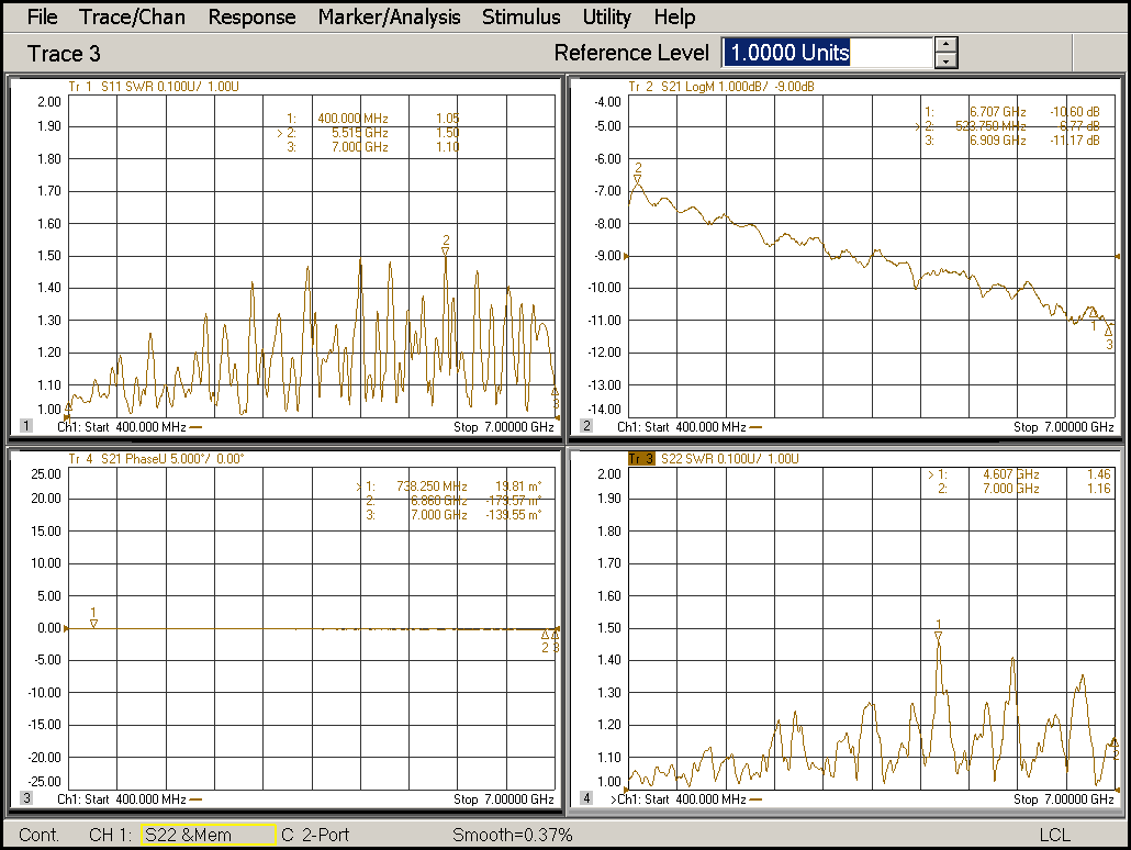
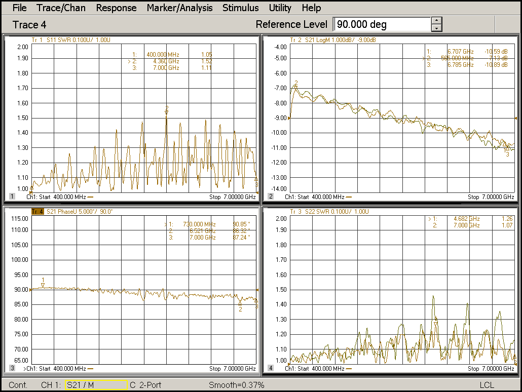
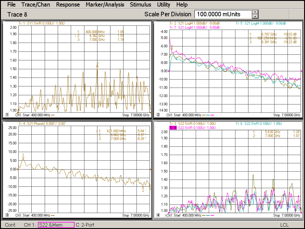
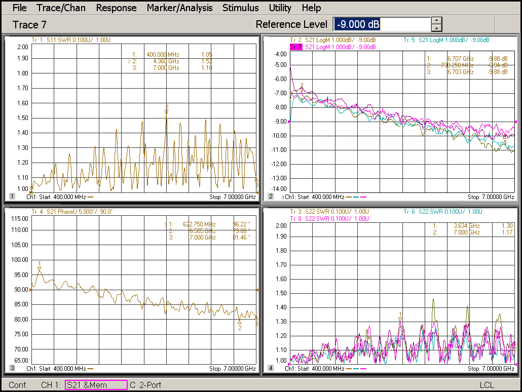
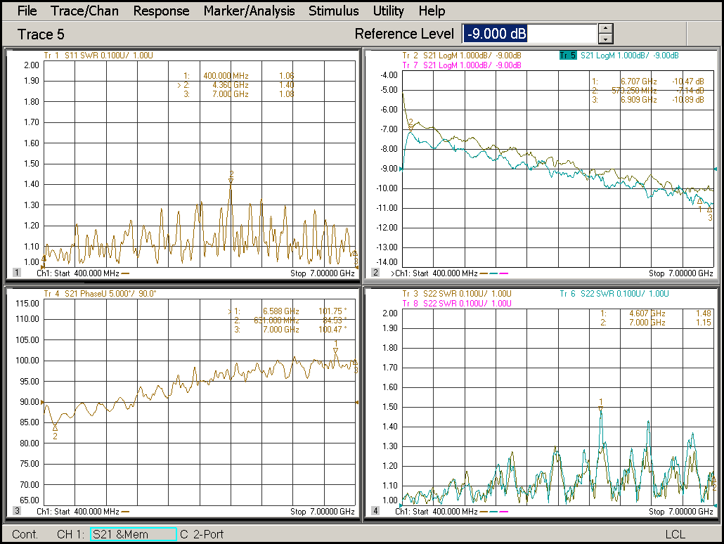
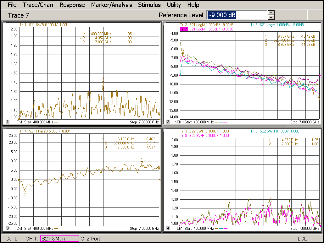
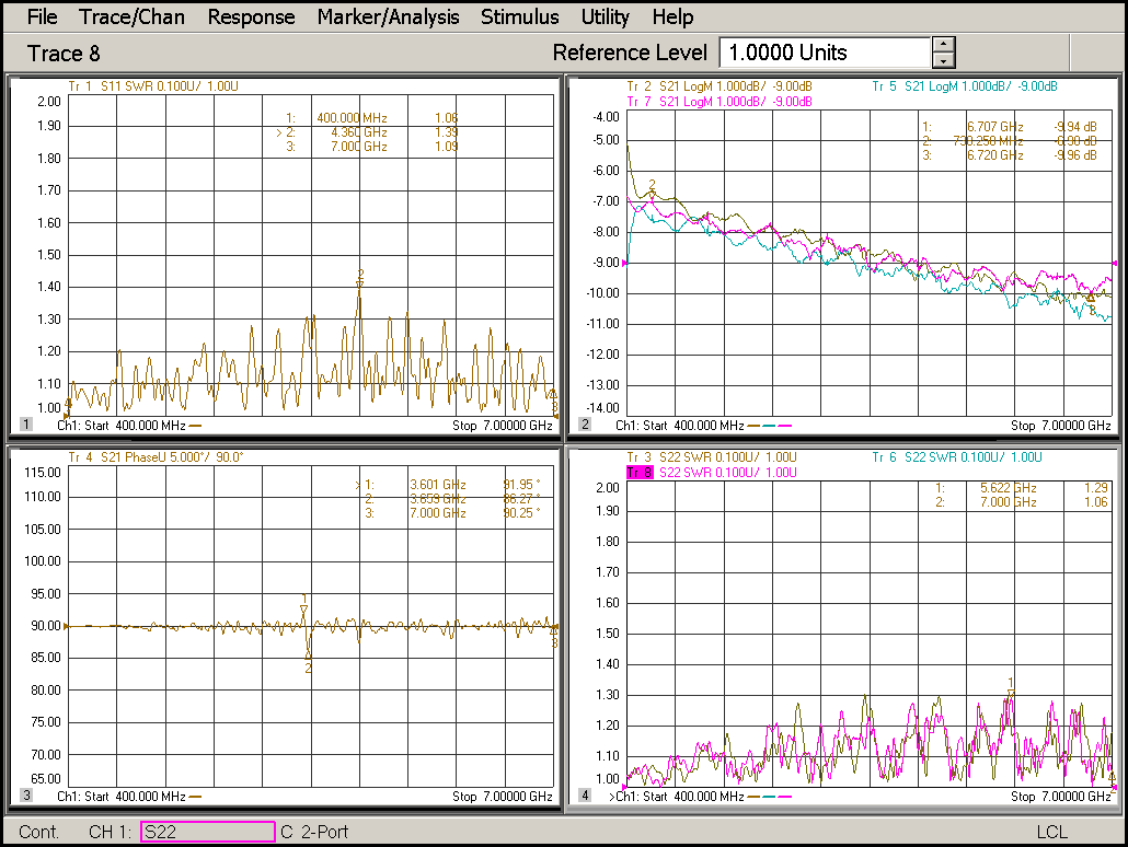
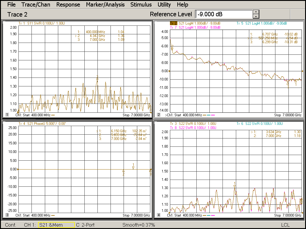
| Leader-mw | Test Data |