
Products
ANT0105_V1 8Ghz Ultra-wideband Omnidirectional Antenna
| Leader-mw | Introduction to 8Ghz Ultra-Wideband Omnidirectional Antenna |
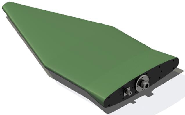
Introducing Leader microwave Tech.,(LEADER-MW) latest innovation in wireless communications technology - the 8Ghz Ultra-Wideband Omnidirectional Antenna. This cutting-edge antenna aims to revolutionize the way we connect and communicate in the digital age. With its advanced technology and superior performance, this antenna is sure to be a game-changer in wireless networking.
8Ghz ultra-wideband omnidirectional antenna provides unparalleled versatility and reliability. Its omnidirectional design enables seamless connectivity in all directions, ensuring consistent signal strength and coverage throughout the range. Whether you're setting up a wireless network in a large office space, warehouse, or outdoor environment, this antenna provides the perfect solution for all your connectivity needs.
One of the main features of this antenna is its ultra-wideband capability, allowing it to operate over a wide frequency range of 8Ghz. This means it can support a variety of wireless technologies and applications, including Wi-Fi, Bluetooth and IoT devices. With this antenna, you can future-proof your wireless network and ensure compatibility with the latest technologies.
Additionally, the 8Ghz ultra-wideband omnidirectional antenna delivers superior performance in terms of signal strength and speed. Whether you're streaming HD video, conducting video conferencing, or transferring large files, this antenna ensures a stable and reliable connection at all times. Its durable construction and weather-resistant design make it suitable for indoor and outdoor use, providing a reliable and consistent connection in any environment.
| Leader-mw | Specification |
ANT0105_V1 20MHz~8GHz
| Frequency Range: | 20-8000MHz |
| Gain, Typ: | ≥0(TYP.) |
| Max. deviation from circularity | ±1.5dB(TYP.) |
| Horizontal radiation pattern: | ±1.0dB |
| Polarization: | vertical polarization |
| VSWR: | ≤ 2.5: 1 |
| Impedance: | 50 OHMS |
| Port Connectors: | N-Female |
| Operating Temperature Range: | -40˚C-- +85 ˚C |
| weight | 1kg |
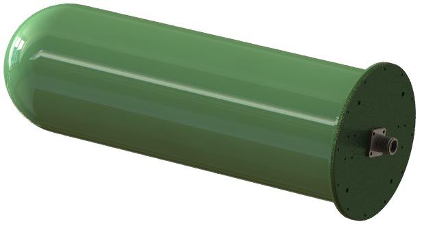
| Surface Color: | Green |
| Outline: | φ144×394 |
Remarks:
Power rating is for load vswr better than 1.20:1
| Leader-mw | Environmental Specifications |
| Operational Temperature | -30ºC~+60ºC |
| Storage Temperature | -50ºC~+85ºC |
| Vibration | 25gRMS (15 degrees 2KHz) endurance, 1 hour per axis |
| Humidity | 100% RH at 35ºc, 95%RH at 40ºc |
| Shock | 20G for 11msec half sine wave,3 axis both directions |
| Leader-mw | Mechanical Specifications |
| Item | materials | surface |
| installation block | stainless steel 304 | passivation |
| flange | 5A06 rust-proof aluminum | Color conductive oxidation |
| Lower pole | 5A06 rust-proof aluminum | Color conductive oxidation |
| Upper pole | 5A06 rust-proof aluminum | Color conductive oxidation |
| gland | 5A06 rust-proof aluminum | Color conductive oxidation |
| patching panel | Red copper | passivation |
| insulating part | nylon | |
| vibrator | 5A06 rust-proof aluminum | Color conductive oxidation |
| Axis 1 | stainless steel | passivation |
| Axis 2 | stainless steel | passivation |
| Rohs | compliant | |
| Weight | 1kg | |
| Packing | Aluminum alloy packing case (customizable) | |
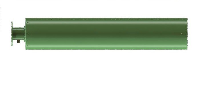
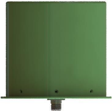
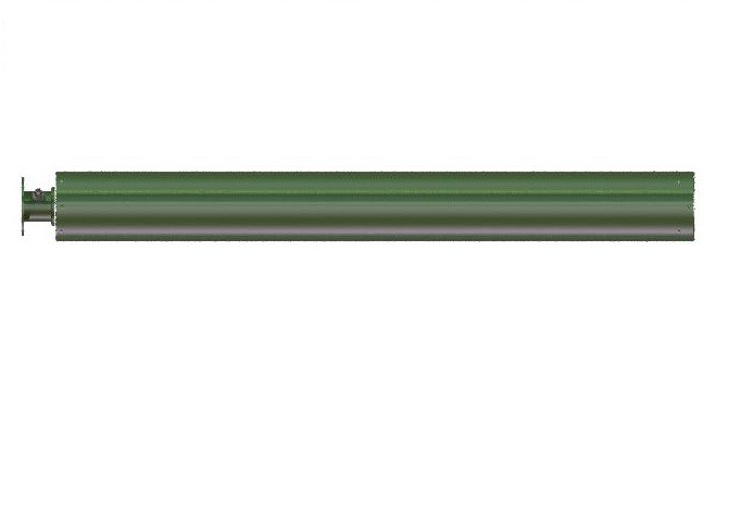
Outline Drawing:
All Dimensions in mm
Outline Tolerances ± 0.5(0.02)
Mounting Holes Tolerances ±0.2(0.008)
All Connectors: N-Female

| Leader-mw | Test Data |
| Leader-mw | Introduction to VSWR |
Parameter VSWR is a measurement method that digitally describes the impedance matching degree of antenna and the circuit or interface it is connected to. The following circuit analysis shows the main calculation process of VSWR:

The meanings of the parameters in the figure are as follows:
Z0: characteristic impedance of signal source circuit;
ZIN: circuit input impedance;
V+ : source incident voltage;
V- : indicates the reflected voltage at the source end.
I+ : signal source incident current;
I- : reflected current at the signal source;
VIN: transmission voltage into the load;
IIN: Transmission current into the load
The VSWR calculation formula is as follows: