Products
Airline Coupler
| Leader-mw |
schematic diagram |

| Leader-mw | Introduction to Broadband Couplers |
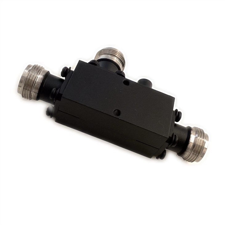
It consists of concentric cylindrical cavity body and cylinder of the main line of the air medium the main signaling pathways, characteristic impedance for 50 ohm.Coupling line including forward coupling line and the reverse coupling line, the structure has the same size, placed above the main signal lines are on the same side and along the axis of the main line is fixed on the coupled microstrip board, coupled microstrip board the plane parallel to the axis with the main line.Coupler shell side of the outer surface along the cavity axis direction, there are two rectangular coupling, coupling line from coupling agent into the mouth cavity in the body.Coupling signal output to the coupled microstrip line by microstrip panels which ports, coupling port connector for MMCX Yin head, the welding is fixed on the microstrip board.Covered the microstrip coupler cover plate.Coupled cavity, the main line, line is the metal material of conductive performance is good, the main line and line coupling surface plating
| Leader-mw | Introduction to Broadband Couplers |
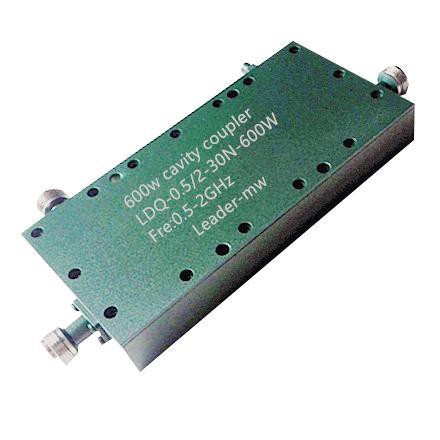
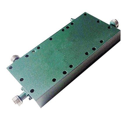
Type NO:LDC-0.5/2-30N Cavity coupler
| Frequency Range: | 500-2000MHz |
| Insertion Loss: | ≤0.2dB |
| Surface Finish | Painted pantone #627 green |
| Configuration | As Below (tolerance±0.3mm) |
| VSWR: | ≤1.35:1 |
| Isolation: | ≥42dB |
| Impedance: | 50 OHMS |
| Connectors : | N-Female |
| Coupling | 30±1.3 |
| Power Handling: | 600W |
Remarks:
1、Not Include Theoretical loss 2.Power rating is for load vswr better than 1.20:1
| Leader-mw | Environmental Specifications |
| Operational Temperature | -30ºC~+60ºC |
| Storage Temperature | -50ºC~+85ºC |
| Vibration | 25gRMS (15 degrees 2KHz) endurance, 1 hour per axis |
| Humidity | 100% RH at 35ºc, 95%RH at 40ºc |
| Shock | 20G for 11msec half sine wave,3 axis both directions |
| Leader-mw | Mechanical Specifications |
| Housing | Aluminum |
| Connector | ternary alloy three-partalloy |
| Female Contact: | gold plated beryllium bronze |
| Rohs | compliant |
| Weight | 0.2kg |
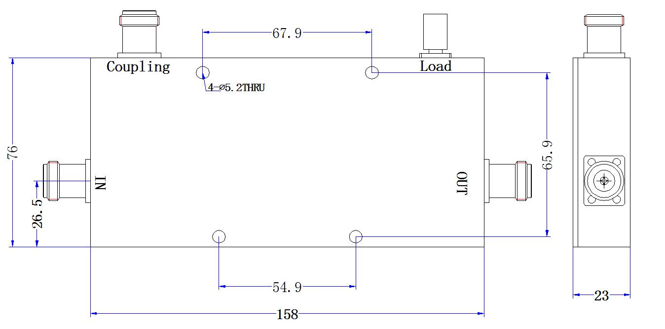
Outline Drawing:
All Dimensions in mm
Outline Tolerances ± 0.5(0.02)
Mounting Holes Tolerances ±0.2(0.008)
All Connectors: N-Female
