Products
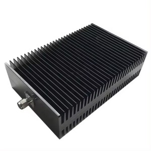
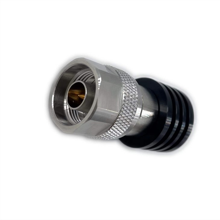
DC-40Ghz,100w power 2.92 Coaxial Teminations
| Leader-mw | Introduction DC-40Ghz 100w Coaxial Terminations With 2.92 Connecter |
The coaxial Terminations is mainly used to absorb the power of RF or microwave system and can be used as a false load of antenna and transmitter terminal. It can also be used as the matching port of multi-port microwave devices such as circulators and directional couplers to ensure the matching of characteristic impedance and accurate measurement. LFZ-DC/40-100W-2.92 series coaxial termination load average power 100W, frequency range DC~40GHz. It has the following characteristics: wide working frequency band, low standing wave coefficient, strong anti-pulse and anti-burn ability
| Leader-mw | Specification |
|
Item |
Specification |
|
Frequency range |
DC ~40GHz |
|
Impedance (Nominal) |
50Ω |
|
Power rating |
100 Watt@25℃ , ,derated linearly to 10W @ 125°C |
|
Peak Power(5 μs) |
1 KW(Max. 5 PI s pulse width, Max. 10% duty cycle) |
|
V.S.W.R (Max) |
1.4 |
|
Connector type |
2.92 male(Input) |
|
dimension |
180*145mm |
|
Temperature Range |
-55℃~ 85℃ |
|
Weight |
0.88KG |
|
Colour |
Brushed black (matte) |
| Leader-mw | Environmental Specifications |
| Operational Temperature | -55ºC~+125ºC |
| Storage Temperature | -55ºC~+125ºC |
| Vibration | 25gRMS (15 degrees 2KHz) endurance, 1 hour per axis |
| Humidity | 100% RH at 35ºc, 95%RH at 40ºc |
| Shock | 20G for 11msec half sine wave,3 axis both directions |
| Leader-mw | Mechanical Specifications |
| Housing | Heat Sinks:Aluminum Black Anodize |
| Connector | Stainless Steel Passivation |
| PIN |
Male:Gold-plated brass 50 micro-inches
|
|
Insulators
|
PEI |
| Weight | 0.88kg |
Outline Drawing:
All Dimensions in mm
Outline Tolerances ± 0.5(0.02)
Mounting Holes Tolerances ±0.2(0.008)
All Connectors: 2.92-Female/2.92-M(IN)

| Leader-mw | VSWR |
|
Frequency |
VSWR |
|
DC-40Ghz |
1.4 |


