Products
DC-6Ghz 2-way Resistive Power Divider
| Leader-mw | Introduction to 2-way Resistive Power Divider |
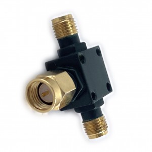
DC-6GHz 2-Way Resistive Power Divider (Model: LPD-DC/6-2s)
The DC-6GHz 2-Way Resistive Power Divider is a high-performance RF component designed to split an input signal into two equal-output paths across a broad frequency range from DC to 6GHz. Ideal for applications requiring wideband operation, such as telecommunications, test and measurement systems, and broadband communication networks, this divider ensures consistent signal integrity with minimal distortion.
Key specifications include an insertion loss of 6 ±0.5 dB, inherent to resistive designs due to power dissipation in internal resistors. Despite this loss, the device excels in precision, offering tight amplitude balance ≤±0.3 dB and phase balance ≤3 degrees, critical for maintaining signal coherence in sensitive systems like phased arrays or balanced mixers. The VSWR ≤1.25 underscores excellent impedance matching, reducing reflections and ensuring stable performance across the entire bandwidth.
Unlike reactive dividers, this resistive variant provides inherent port isolation without additional components, simplifying design while remaining compact and cost-effective. Its robust construction ensures reliability in demanding environments, making it suitable for both laboratory and field applications.
While resistive dividers typically trade higher insertion loss for broadband performance and isolation, the LPD-DC/6-2s model balances these traits with exceptional amplitude/phase consistency and low VSWR. Whether used in signal distribution, power monitoring, or calibration setups, this power divider delivers dependable, high-quality performance tailored for modern RF systems requiring accuracy and wide frequency coverage.
| Leader-mw | Specification |
| No. | Parameter | Minimum | Typical | Maximum | Units |
| 1 | Frequency range |
DC |
- |
6 |
GHz |
| 2 | Insertion Loss |
- |
- |
0.5 |
dB |
| 3 | Phase Balance: |
- |
±3 |
dB |
|
| 4 | Amplitude Balance |
- |
±0.3 |
dB |
|
| 5 | VSWR |
- |
1.25 |
- |
|
| 6 | Power |
1 |
W cw |
||
| 7 | Isolation |
- |
|
dB |
|
| 8 | Impedance |
- |
50 |
- |
Ω |
| 9 | Connecter |
SMA-F&SMA-M |
|||
| 10 | Preferred finish |
SLIVER/GREEN/YELLOW/BLUE/BLACK |
|||
Remarks:
1、Not Include Theoretical loss 6 db 2.Power rating is for load vswr better than 1.20:1
| Leader-mw | Environmental Specifications |
| Operational Temperature | -30ºC~+60ºC |
| Storage Temperature | -50ºC~+85ºC |
| Vibration | 25gRMS (15 degrees 2KHz) endurance, 1 hour per axis |
| Humidity | 100% RH at 35ºc, 95%RH at 40ºc |
| Shock | 20G for 11msec half sine wave,3 axis both directions |
| Leader-mw | Mechanical Specifications |
| Housing | Aluminum |
| Connector | ternary alloy three-partalloy |
| Female Contact: | gold plated beryllium bronze |
| Rohs | compliant |
| Weight | 0.05kg |
Outline Drawing:
All Dimensions in mm
Outline Tolerances ± 0.5(0.02)
Mounting Holes Tolerances ±0.2(0.008)
All Connectors: In:SMA-M,out:SMA-Female

| Leader-mw | Test Data |


