Products
Drop In 90 Degree Hybrid Coupler
| Leader-mw | Introduction to 6-18Ghz drop in hybrid coupler |
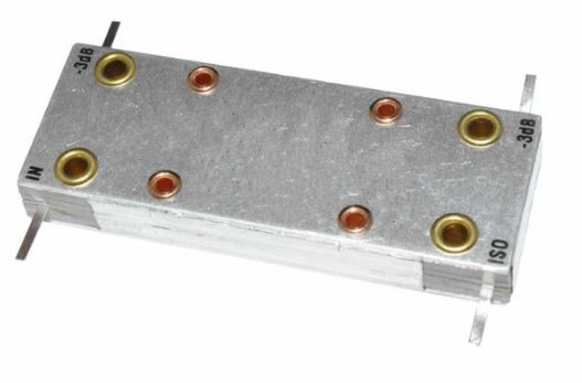
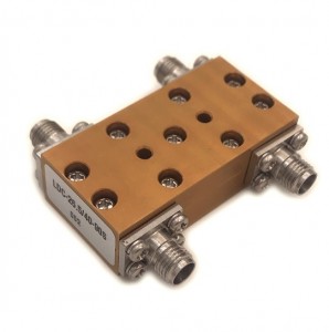
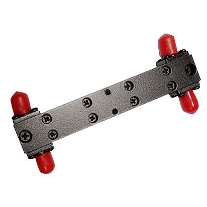
Drop in 90 degree hybrid coupler
A drop-in hybrid coupler is a type of passive microwave component that splits the input power into two or more output ports with minimal loss and good isolation between the output ports. It operates over a wide frequency range, typically from 6 to 18 GHz, which encompasses the C, X, and Ku bands commonly used in various communication systems.
The coupler is designed to handle an average power of up to 5W, making it suitable for use in medium-power applications such as test equipment, signal distribution networks, and other telecommunication infrastructures. Its compact size and easy-to-install design make it a popular choice for integrators looking to minimize system complexity while ensuring reliable performance.
The key features of this coupler include low insertion loss, high return loss, and excellent VSWR (Voltage Standing Wave Ratio) performance, all of which contribute to maintaining signal integrity across the specified frequency band. Additionally, the coupler's broadband nature allows it to accommodate multiple channels within its operational range, providing flexibility in system design.
In summary, the drop-in hybrid coupler with a 6-18 GHz frequency range and 5W power handling capability is an essential component for engineers working on complex RF and microwave systems. Its robust construction and versatile performance make it a valuable asset for any application requiring precise power division and signal management.
| Leader-mw | Specification |
| Specification | |||||
| No. | Parameter | Minimum | Typical | Maximum | Units |
| 1 | Frequency range | 6 | - | 18 | GHz |
| 2 | Insertion Loss | - | - | 0.75 | dB |
| 3 | Phase Balance: | - | - | ±5 | dB |
| 4 | Amplitude Balance | - | - | ±0.7 | dB |
| 5 | Isolation | 15 | - | dB | |
| 6 | VSWR | - | - | 1.5 | - |
| 7 | Power | 5 | W cw | ||
| 8 | Operating Temperature Range | -40 | - | +85 | ˚C |
| 9 | Impedance | - | 50 | - | Q |
| 10 | Connecter | Drop in | |||
| 11 | Preferred finish | Black/yellow/green/sliver/blue | |||
| Leader-mw | Environmental Specifications |
| Operational Temperature | -40ºC~+85ºC |
| Storage Temperature | -50ºC~+105ºC |
| Altitude | 30,000 ft. (Epoxy Sealed Controlled environment) |
| 60,000 ft. 1.0psi min (Hermetically Sealed Un-controlled environment) (Optional) | |
| Vibration | 25gRMS (15 degrees 2KHz) endurance, 1 hour per axis |
| Humidity | 100% RH at 35ºc, 95%RH at 40ºc |
| Shock | 20G for 11msec half sine wave,3 axis both directions |
| Leader-mw | Mechanical Specifications |
| Housing | Aluminum |
| Connector | strip line |
| Rohs | compliant |
| Weight | 0.1kg |
| Leader-mw | Outline Drawing |
All Dimensions in mm
Outline Tolerances ± 0.5(0.02)
Mounting Holes Tolerances ±0.2(0.008)
All Connectors: Drop in

| Leader-mw | Test data |


