射频

Products

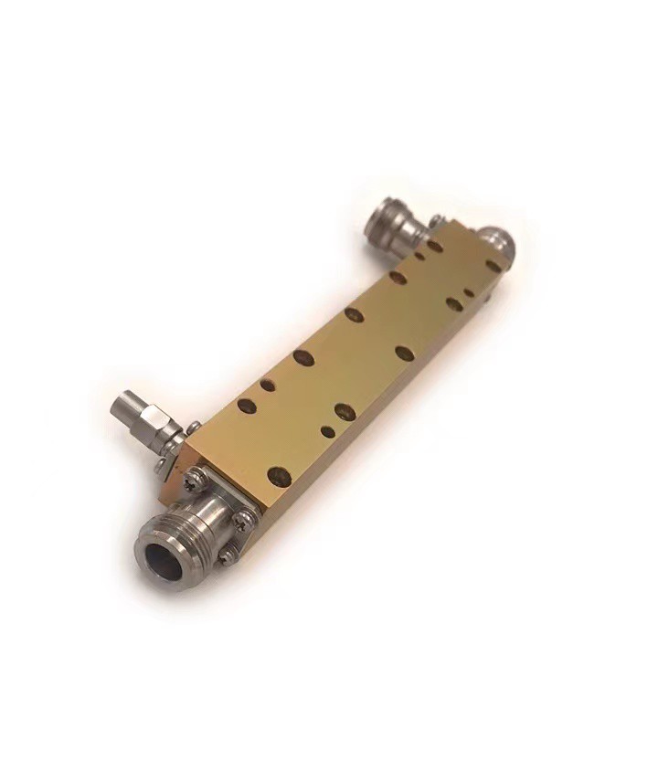
dual directional coupler 0.5-40Ghz

Type:LDDC-0.5/40-10S

Frequency range:0.5-40Ghz

Nominal Coupling:10±1.5dB

Insertion Loss:6.0dB

connecter:2.92-F


Product Detail

Product Tags

Leader-mw Introduction to 40Ghz dual directional Couplers

Leader-mw LDDC-0.5/40-10S is a high-performance dual directional coupler designed for use in telecommunications and microwave applications. This device features a coupling factor of 10dB, making it ideal for signal monitoring and measurement purposes without significantly affecting the main transmission line's performance. The "dual directional" aspect refers to its ability to monitor signals traveling in both directions along the transmission line, providing comprehensive insight into system behavior.

With a frequency range covering from 0.5 to 40GHz, this coupler supports a wide spectrum of operations, accommodating various wireless communication standards and data rates. Its broad bandwidth ensures compatibility with diverse applications, from basic RF testing setups to complex satellite communications systems.

The LDDC-0.5/40-10S boasts low insertion loss and high return loss, ensuring minimal interference with the primary signal path while maintaining signal integrity. These characteristics are crucial for maintaining the quality and reliability of communication links, especially in environments where signal purity and strength are paramount.

Constructed with durability and precision in mind, this coupler incorporates high-quality materials and advanced manufacturing techniques to guarantee long-lasting performance even under harsh operating conditions. It is suitable for integration into both indoor laboratory equipment and outdoor infrastructure, such as base stations or antenna feed networks.

In summary, the LDDC-0.5/40-10S dual directional coupler stands out as a versatile and reliable component for professionals seeking accurate signal analysis across a wide frequency range. Its combination of technical excellence, broadband coverage, and robust build makes it an invaluable tool in the realm of modern telecommunications engineering and research.

Leader-mw Specification

Type NO:LDC-0.5/40-10s

No. Parameter Minimum Typical Maximum Units
1 Frequency range 0.5 40 GHz
2 Nominal Coupling 10 dB
3 Coupling Accuracy ±1.5 dB
4 Coupling Sensitivity to Frequency ±1.2 dB
5 Insertion Loss 6 dB
6 Directivity  10 dB
7 VSWR 1.7 -
8 Power 20 W
9 Operating Temperature Range -40 +85 ˚C
10 Impedance - 50 - Ω

Remarks:

1、Not Include Theoretical loss 0.46db  2.Power rating is for load vswr better than 1.20:1

Leader-mw Environmental Specifications
Operational Temperature -30ºC~+60ºC
Storage Temperature -50ºC~+85ºC
Vibration 25gRMS (15 degrees 2KHz) endurance, 1 hour per axis
Humidity 100% RH at 35ºc, 95%RH at 40ºc
Shock 20G for 11msec half sine wave,3 axis both directions
Leader-mw Mechanical Specifications
Housing Aluminum
Connector stainless steel
Female Contact: gold plated beryllium bronze
Rohs compliant
Weight 0.15kg


Outline Drawing:

All Dimensions in mm

Outline Tolerances ± 0.5(0.02)

Mounting Holes Tolerances ±0.2(0.008)

All Connectors: 2.92-Female

1731577087544
Leader-mw Test Data

  • Previous:
  • Next: