
Products
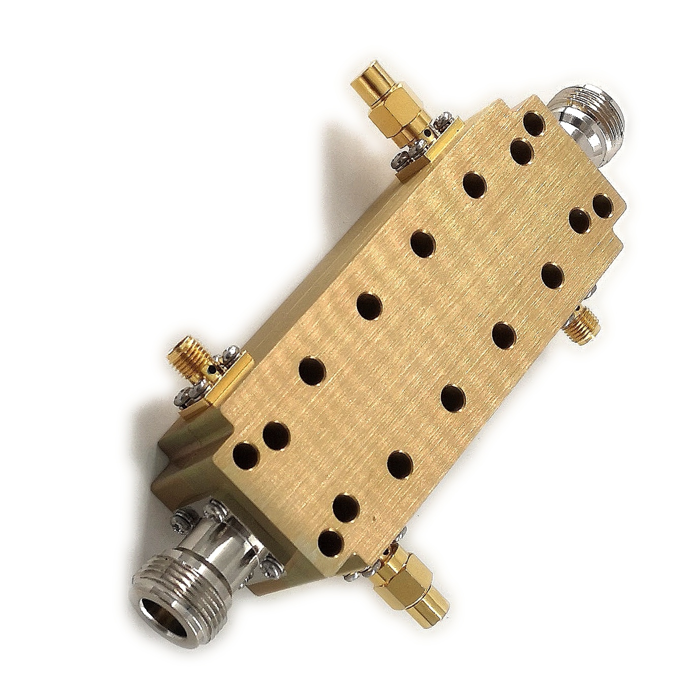
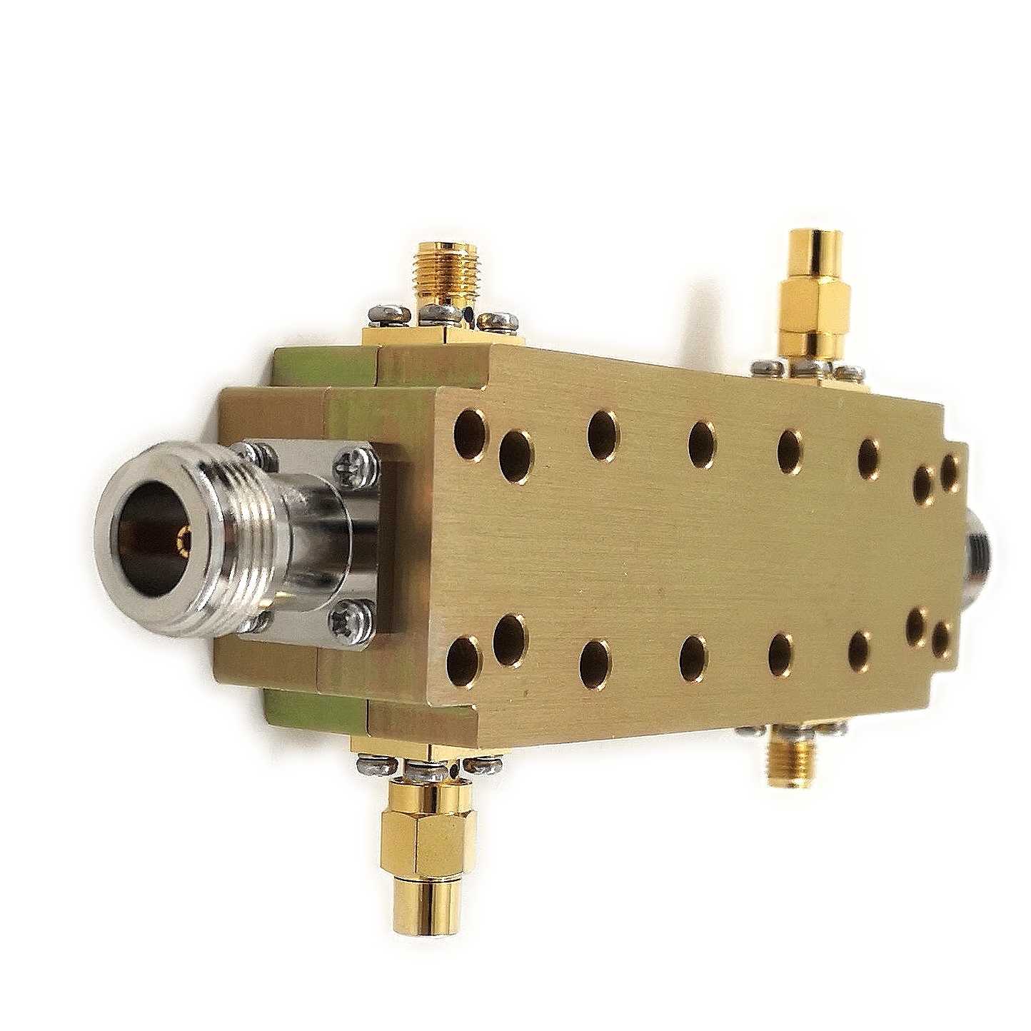

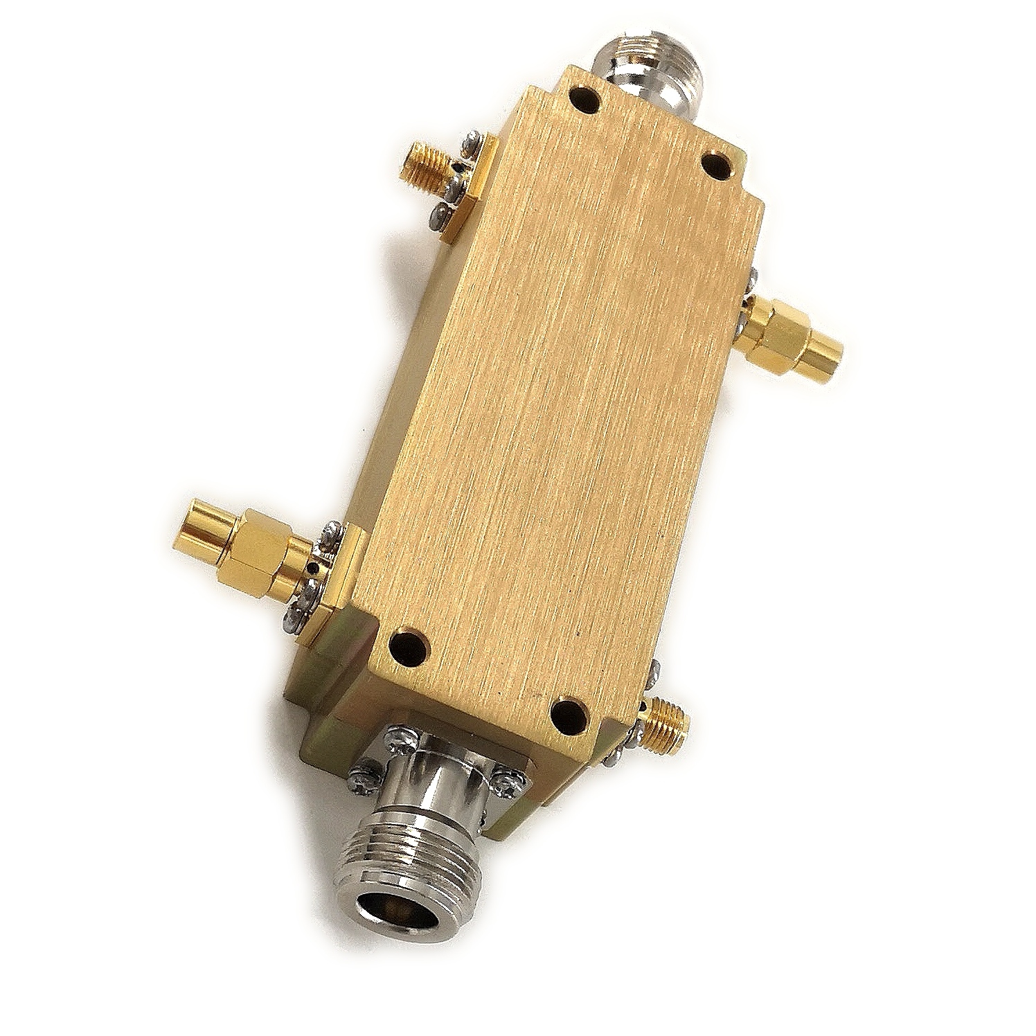
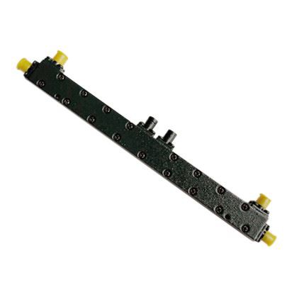
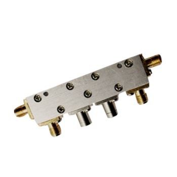
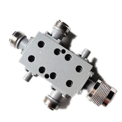
LDDC-0.5/2-40N-600W Dual Directional Coupler With N Connecter
| Leader-mw | Introduction to Dual Directional Coupler With N Connecter |
Chengdu leader microwave Tech.,(leader-mw) the bidirectional coupler with N connector, the perfect solution for all your RF signal measurement and monitoring needs. This innovative coupler delivers a high level of performance and reliability, making it an essential tool for engineers and technicians working in telecommunications, radar systems and RF testing.
With its N-connector interface, our bidirectional couplers are compatible with a wide range of instruments and equipment, ensuring seamless integration into your existing setup. The coupler features a compact and rugged design suitable for both laboratory and field applications. Its rugged construction and high-quality materials ensure long-term durability and consistent performance in a variety of operating environments.
Dual directional couplers are designed to accurately measure the power level and direction of RF signals, allowing precise analysis and monitoring of signal transmission and reflections. The bidirectional design allows simultaneous measurement of forward and reflected power, providing a complete understanding of RF system and component behavior.
Equipped with advanced internal circuitry and components, our couplers provide exceptional accuracy and repeatability, ensuring reliable and consistent measurement results. High isolation between input and output ports minimizes signal interference and distortion, while low insertion loss maximizes signal transmission efficiency through the coupler.
| Leader-mw | Specification |
Type No:LDDC-0.5/2-40N-600-1 Dual Directional Coupler with N connecter
| No. | Parameter | Minimum | Typical | Maximum | Units |
| 1 | Frequency range | 0.5 | 2 | GHz | |
| 2 | Nominal Coupling | 40 | dB | ||
| 3 | Coupling Accuracy | 40±1 | dB | ||
| 4 | Coupling Sensitivity to Frequency | ±0.5 | ±0.8 | dB | |
| 5 | Insertion Loss | 0.3 | dB | ||
| 6 | Directivity | 20 | dB | ||
| 7 | VSWR | 1.2 | - | ||
| 8 | Power | 600 | W | ||
| 9 | Operating Temperature Range | -25 | +55 | ˚C | |
| 10 | Impedance | - | 50 | - | Ω |
Remarks:
1、Not Include Theoretical loss 13.4db 2.Power rating is for load vswr better than 1.20:1
| Leader-mw | Environmental Specifications |
| Operational Temperature | -30ºC~+60ºC |
| Storage Temperature | -50ºC~+85ºC |
| Vibration | 25gRMS (15 degrees 2KHz) endurance, 1 hour per axis |
| Humidity | 100% RH at 35ºc, 95%RH at 40ºc |
| Shock | 20G for 11msec half sine wave,3 axis both directions |
| Leader-mw | Mechanical Specifications |
| Housing | Aluminum |
| Connector | ternary alloy three-partalloy |
| Female Contact: | gold plated beryllium bronze |
| Rohs | compliant |
| Weight | 0.5kg |
Outline Drawing:
All Dimensions in mm
Outline Tolerances ± 0.5(0.02)
Mounting Holes Tolerances ±0.2(0.008)
All Connectors: N-Female

| Leader-mw | Test Data |