Products
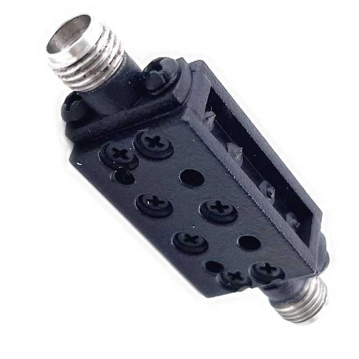
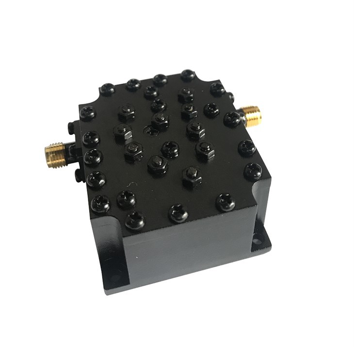
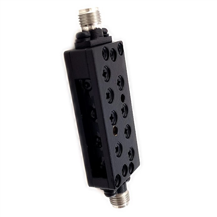
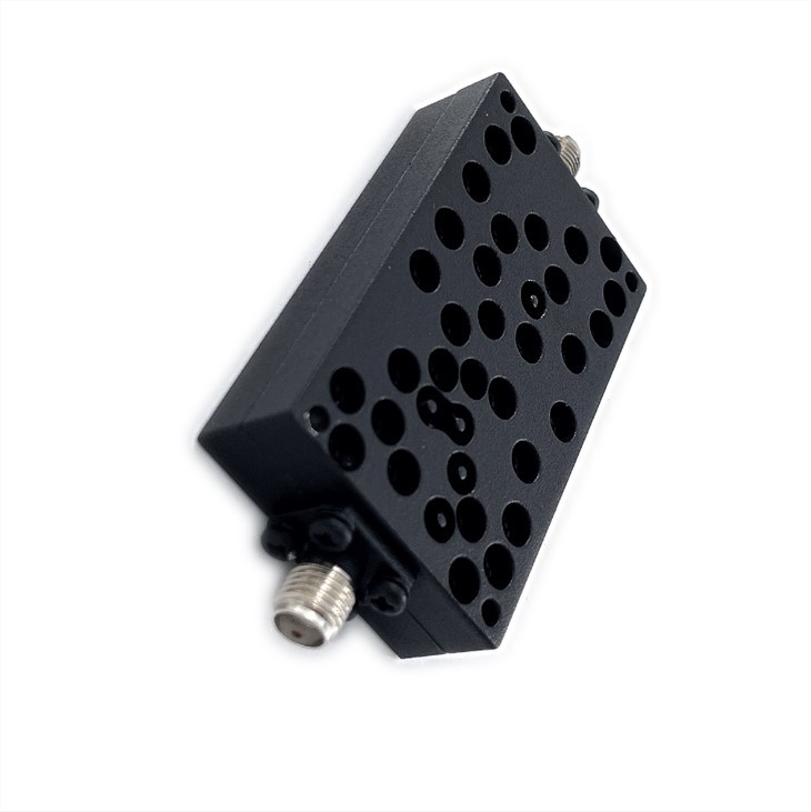
LBF-33.5/13.5-2S band pass cavity filter
| Leader-mw | Introduction to LBF-33.5/13.5-2S Band Pass Cavity Filter |
The LBF-33.5/13.5-2S Band Pass Cavity Filter is a high-performance component designed for use in microwave communication systems operating within the frequency range of 26 to 40 GHz. This filter is optimized for applications in the highly demanding millimeter-wave band, where precision and reliability are critical.
The filter features a 2.92mm connector, which is a standard in the industry for its reliability and ease of use. This connector type ensures that the filter can be easily integrated into existing systems without the need for additional adapters or transitions, simplifying the assembly process and reducing potential points of signal loss or reflection.
Internally, the LBF-33.5/13.5-2S utilizes cavity resonator technology to create a band-pass filter with steep cut-off slopes and excellent out-of-band rejection. This technology allows only a defined range of frequencies to pass through while attenuating signals outside this band. The result is improved signal purity and reduced interference for clearer communications.
With a design optimized for low insertion loss and high Q-factor, the LBF-33.5/13.5-2S provides efficient transmission of desired frequencies while minimizing energy losses. Its compact size and robust construction make it suitable for both fixed installations and mobile platforms, including satellite communication systems, radar technology, and wireless infrastructure.
In summary, the LBF-33.5/13.5-2S Band Pass Cavity Filter offers system designers and integrators a reliable solution for high-frequency applications requiring precise frequency control and superior performance across a wide bandwidth. Its compatibility with standard 2.92mm connectors and robust cavity design ensures seamless integration and optimal performance in even the most demanding millimeter-wave environments.
| Leader-mw | Specification |
| Frequency Range | 26.5-40GHz |
| Insertion Loss | ≤1.0dB |
| VSWR | ≤1.6:1 |
| Rejection | ≥10dB@20-26Ghz, ≥50dB@DC-25Ghz, |
| Power Handing | 1W |
| Port Connectors | SMA-Female |
| Surface Finish | Black |
| Configuration | As Below (tolerance±0.5mm) |
| colour | black/Sliver/green/yellow |
Remarks:
Power rating is for load vswr better than 1.20:1
| Leader-mw | Environmental Specifications |
| Operational Temperature | -30ºC~+60ºC |
| Storage Temperature | -50ºC~+85ºC |
| Vibration | 25gRMS (15 degrees 2KHz) endurance, 1 hour per axis |
| Humidity | 100% RH at 35ºc, 95%RH at 40ºc |
| Shock | 20G for 11msec half sine wave,3 axis both directions |
| Leader-mw | Mechanical Specifications |
| Housing | Aluminum |
| Connector | stainless steel |
| Female Contact: | gold plated beryllium bronze |
| Rohs | compliant |
| Weight | 0.15kg |
Outline Drawing:
All Dimensions in mm
Outline Tolerances ± 0.5(0.02)
Mounting Holes Tolerances ±0.2(0.008)
All Connectors: 2.92-Female


