
Products


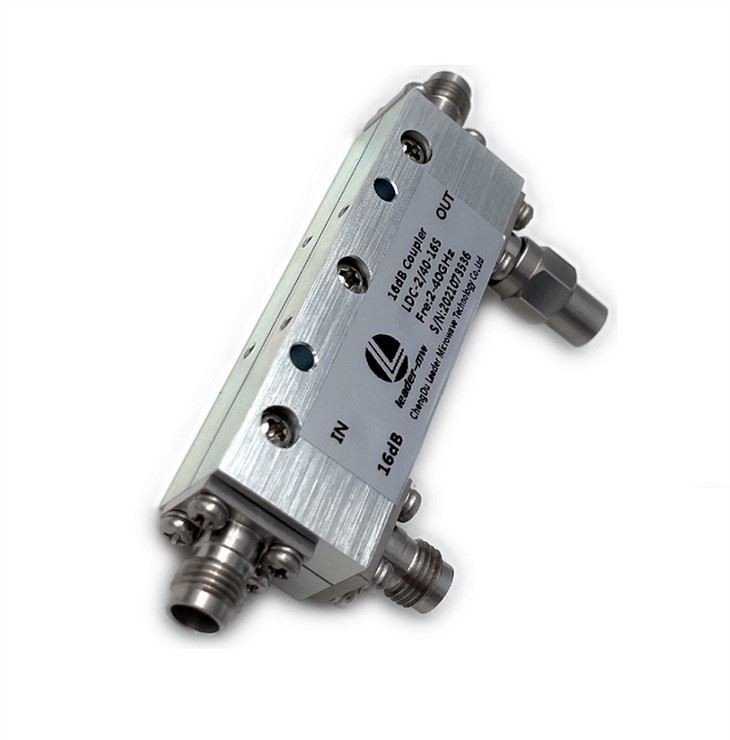
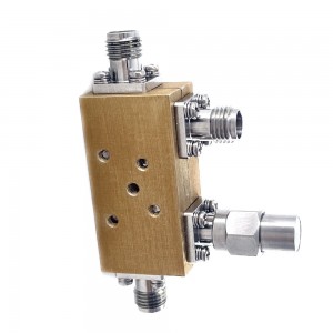
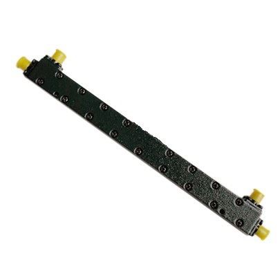
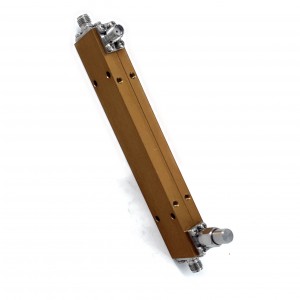
LDC-0.5/40-10S ka band Ultra wideband coupler
| Leader-mw | Introduction to 40Ghz Couplers |
| Leader-mw | Specification |
Type NO:LDC-0.5/40-10s
| No. | Parameter | Minimum | Typical | Maximum | Units |
| 1 | Frequency range | 0.5 | 40 | GHz | |
| 2 | Nominal Coupling | 10 | dB | ||
| 3 | Coupling Accuracy | ±1.5 | dB | ||
| 4 | Coupling Sensitivity to Frequency | ±0.7 | ±1 | dB | |
| 5 | Insertion Loss | 3.2 | dB | ||
| 6 | Directivity | 10 | 15 | dB | |
| 7 | VSWR | 1.6 | - | ||
| 8 | Power | 50 | W | ||
| 9 | Operating Temperature Range | -40 | +85 | ˚C | |
| 10 | Impedance | - | 50 | - | Ω |
Remarks:
1、Not Include Theoretical loss 0.46db 2.Power rating is for load vswr better than 1.20:1
| Leader-mw | Environmental Specifications |
| Operational Temperature | -30ºC~+60ºC |
| Storage Temperature | -50ºC~+85ºC |
| Vibration | 25gRMS (15 degrees 2KHz) endurance, 1 hour per axis |
| Humidity | 100% RH at 35ºc, 95%RH at 40ºc |
| Shock | 20G for 11msec half sine wave,3 axis both directions |
| Leader-mw | Mechanical Specifications |
| Housing | Aluminum |
| Connector | stainless steel |
| Female Contact: | gold plated beryllium bronze |
| Rohs | compliant |
| Weight | 0.25kg |
Outline Drawing:
All Dimensions in mm
Outline Tolerances ± 0.5(0.02)
Mounting Holes Tolerances ±0.2(0.008)
All Connectors: 2.92-Female

| Leader-mw | Test Data |