Products
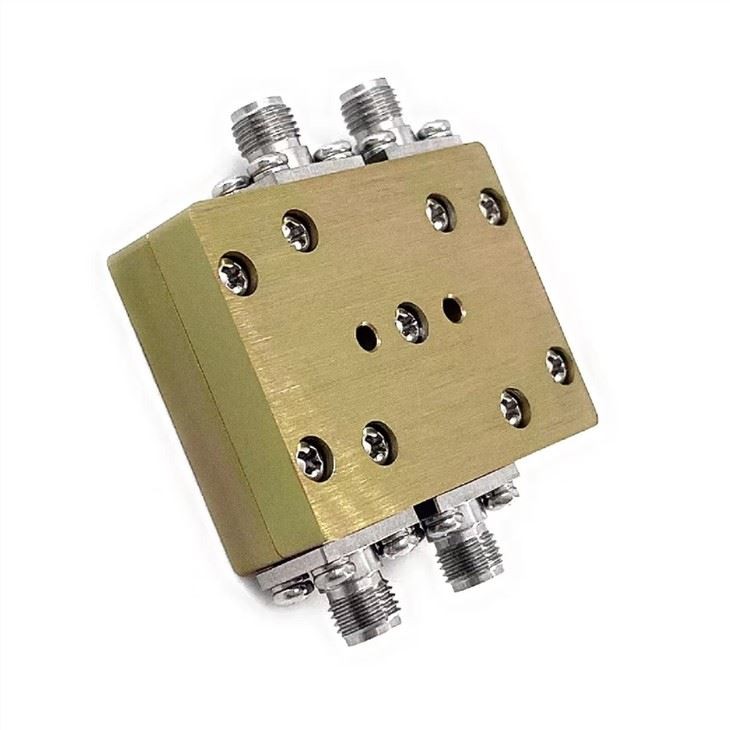
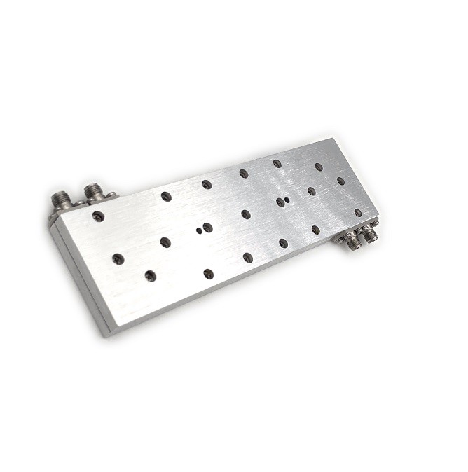
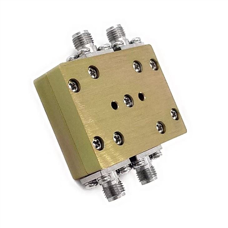
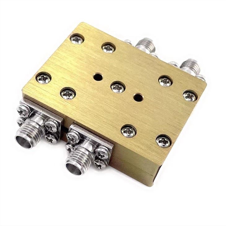
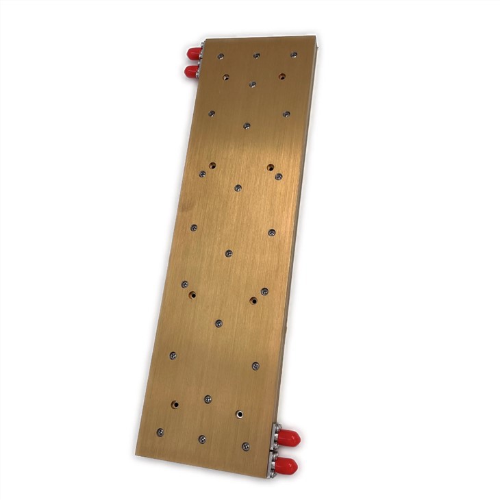
LDC-1/2-180S L band 180 Degree hybrid coupler
| Leader-mw | Introduction to 1-2Ghz hybrid Couplers |
Introducing the LDC-1/2-180S 180 Degree Hybrid Coupler, a cutting-edge solution for RF signal distribution and combining applications. This innovative coupler is designed to provide exceptional performance and reliability in a wide range of communication systems, making it an ideal choice for demanding RF engineering projects.
The LDC-1/2-180S 180 Degree Hybrid Coupler features a compact and robust design, making it suitable for use in both indoor and outdoor environments. Its high-quality construction ensures excellent durability and long-term performance, even in challenging operating conditions. With a frequency range of 800-2500 MHz, this coupler is versatile and can be used in various RF communication systems.
One of the key advantages of the LDC-1/2-180S 180 Degree Hybrid Coupler is its exceptional electrical performance. It offers low insertion loss and high isolation, ensuring minimal signal degradation and interference. This makes it an ideal choice for applications where signal integrity is critical, such as in wireless communication networks, radar systems, and satellite communication systems.
Furthermore, the LDC-1/2-180S 180 Degree Hybrid Coupler is designed for easy integration into existing RF systems. Its compact form factor and versatile mounting options make it simple to install and configure, saving time and effort during system deployment. Additionally, its high power handling capability makes it suitable for high-power RF applications, further expanding its utility in various scenarios.
In conclusion, the LDC-1/2-180S 180 Degree Hybrid Coupler is a state-of-the-art solution for RF signal distribution and combining. Its exceptional performance, robust construction, and versatile design make it an excellent choice for a wide range of communication systems. Whether you are designing a new RF network or upgrading an existing system, the LDC-1/2-180S 180 Degree Hybrid Coupler is the perfect choice for reliable and high-performance RF signal management.
| Leader-mw | specification |
| No. | Parameter | Minimum | Typical | Maximum | Units |
| 1 | Frequency range |
1 |
- |
2 |
GHz |
| 2 | Insertion Loss |
- |
- |
0.5 |
dB |
| 3 | Phase Balance: |
- |
±8 |
dB |
|
| 4 | Amplitude Balance |
- |
±0.7 |
dB |
|
| 5 | VSWR |
- |
1.35 |
- |
|
| 6 | Power |
20w |
W cw |
||
| 7 | Isolation |
20 |
- |
dB |
|
| 8 | Impedance |
- |
50 |
- |
Ω |
| 9 | Connecter |
SMA-F |
|||
| 10 | Preferred finish |
BLACK/YELLOW/BLUE/GREEN/SLIVER |
|||
Remarks:
1、Not Include Theoretical loss 3db 2.Power rating is for load vswr better than 1.20:1
| Leader-mw | Environmental Specifications |
| Operational Temperature | -30ºC~+60ºC |
| Storage Temperature | -50ºC~+85ºC |
| Vibration | 25gRMS (15 degrees 2KHz) endurance, 1 hour per axis |
| Humidity | 100% RH at 35ºc, 95%RH at 40ºc |
| Shock | 20G for 11msec half sine wave,3 axis both directions |
| Leader-mw | Mechanical Specifications |
| Housing | Aluminum |
| Connector | ternary alloy three-partalloy |
| Female Contact: | gold plated beryllium bronze |
| Rohs | compliant |
| Weight | 0.10kg |
Outline Drawing:
All Dimensions in mm
Outline Tolerances ± 0.5(0.02)
Mounting Holes Tolerances ±0.2(0.008)
All Connectors: SMA-Female

| Leader-mw | Test Data |


| Leader-mw | Delivery |

| Leader-mw | Application |


