Products
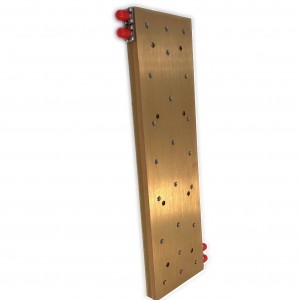
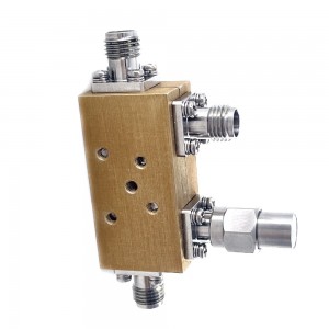
LDC-1/26.5-30S 1-26.5Ghz 30dB directional coupler
| Leader-mw | Introduction to LDC-1/26.5-30S 1-26.5Ghz 30dB directional coupler |
LEADER-MW 30dB Directional Coupler in the 1-26.5 GHz frequency range with a directivity of 13dB is a critical component often used in microwave and RF systems for signal sampling and monitoring. This type of coupler is designed to selectively sample a portion of the power from a transmission line, providing an output that is proportional to the incident power while maintaining high isolation between the input and output ports.
The 30dB coupling level indicates that the coupler will extract 1/1000th of the power from the main signal path, which is useful for applications where minimal signal disruption is essential. The 1-26.5 GHz operating range makes this coupler suitable for a wide array of applications, including telecommunications, radar systems, and satellite communications, as it encompasses many standard communication bands.
With a directivity of 13dB, the coupler effectively minimizes the leakage of power from the output port back into the input port, ensuring that the sampled signal remains accurate and uncontaminated by reflections or noise. This high directivity contributes to the overall performance and reliability of the coupler in complex RF systems, where precision and signal integrity are paramount.
| Leader-mw | Specification |
Type NO:LDC-1/26.5-30S
| No. | Parameter | Minimum | Typical | Maximum | Units |
| 1 | Frequency range | 1 | 26.5 | GHz | |
| 2 | Nominal Coupling | 30 | dB | ||
| 3 | Coupling Accuracy | ±0.6 | dB | ||
| 4 | Coupling Sensitivity to Frequency | ±0.7 | dB | ||
| 5 | Insertion Loss | 1.1 | dB | ||
| 6 | Directivity | 13 | dB | ||
| 7 | VSWR | 1.5 | - | ||
| 8 | Power | 50 | W | ||
| 9 | Operating Temperature Range | -40 | +85 | ˚C | |
| 10 | Impedance | - | 50 | - | Ω |
Remarks:
1.Include Theoretical loss 0.004db 2.Power rating is for load vswr better than 1.20:1
| Leader-mw | Environmental Specifications |
| Operational Temperature | -30ºC~+60ºC |
| Storage Temperature | -50ºC~+85ºC |
| Vibration | 25gRMS (15 degrees 2KHz) endurance, 1 hour per axis |
| Humidity | 100% RH at 35ºc, 95%RH at 40ºc |
| Shock | 20G for 11msec half sine wave,3 axis both directions |
| Leader-mw | Mechanical Specifications |
| Housing | Aluminum |
| Connector | stainless steel |
| Female Contact: | gold plated beryllium bronze |
| Rohs | compliant |
| Weight | 0.15 |
Outline Drawing:
All Dimensions in mm
Outline Tolerances ± 0.5(0.02)
Mounting Holes Tolerances ±0.2(0.008)
All Connectors: SMA-Female

| Leader-mw | Test Data |


