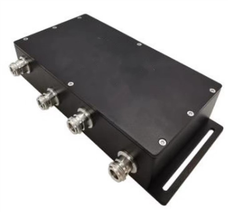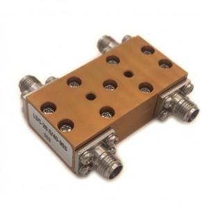
Products
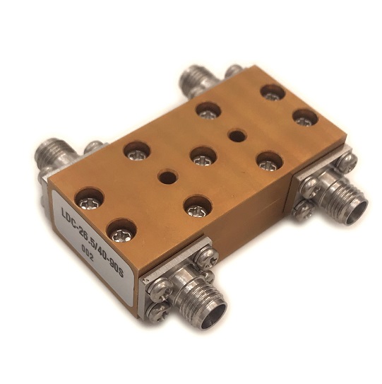
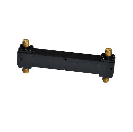
LDC-5/50-90S 50Ghz 90degree hybrid combiner
| Leader-mw | Introduction to Broadband hybrid Couplers |
LDC-5/50-90S hybrid couplers are typically constructed using high-quality materials and precision manufacturing techniques to ensure reliability and performance in demanding environments. They may feature ruggedized designs for military or outdoor applications.
**Connector Types:**
- The connectors at the input and output ports are often standardized to industry specifications like SMA, N-type, or other common RF connectors for easy integration into existing systems.
**Applications:**
- The LDC-5/50-90S coupler is versatile and can be used in various applications including but not limited to balanced mixers, modulators, demodulators, phase shifters, and as part of complex RF front-end modules.
### Application Examples:
- **Telecommunications:** In satellite communication systems where precise phase control is crucial.
- **Radar Systems:** For phased array antennas where controlled phase distribution among elements is required.
- **Microwave Test Equipment:** As part of signal generation and analysis setups needing accurate phase relationships.
- **Aerospace and Defense:** Used in avionics and communication systems demanding high reliability and performance under extreme conditions.
Overall, the LDC-5/50-90S Degree RF microwave hybrid coupler is a critical component for engineers working with microwave frequencies, providing essential functionality for signal routing, phase management, and system integration in advanced communication and sensing systems.
| Leader-mw | specification |
| No. | Parameter | Minimum | Typical | Maximum | Units |
| 1 | Frequency range |
5 |
- |
50 |
GHz |
| 2 | Insertion Loss |
- |
- |
2.8 |
dB |
| 3 | Phase Balance: |
- |
±10 |
dB |
|
| 4 | Amplitude Balance |
- |
±1.4 |
dB |
|
| 5 | VSWR |
- |
2.1(Input) |
- |
|
| 6 | Power |
5w |
W cw |
||
| 7 | Isolation |
11 |
- |
dB |
|
| 8 | Impedance |
- |
50 |
- |
Ω |
| 9 | Connecter |
2.4-F |
|||
| 10 | Preferred finish |
BLACK/YELLOW/BLUE/GREEN/SLIVER |
|||
Remarks:
1、Not Include Theoretical loss 3db 2.Power rating is for load vswr better than 1.20:1
| Leader-mw | Environmental Specifications |
| Operational Temperature | -30ºC~+60ºC |
| Storage Temperature | -50ºC~+85ºC |
| Vibration | 25gRMS (15 degrees 2KHz) endurance, 1 hour per axis |
| Humidity | 100% RH at 35ºc, 95%RH at 40ºc |
| Shock | 20G for 11msec half sine wave,3 axis both directions |
| Leader-mw | Mechanical Specifications |
| Housing | Aluminum |
| Connector | ternary alloy three-partalloy,stainless steel |
| Female Contact: | gold plated beryllium bronze |
| Rohs | compliant |
| Weight | 0.10kg |
Outline Drawing:
All Dimensions in mm
Outline Tolerances ± 0.5(0.02)
Mounting Holes Tolerances ±0.2(0.008)
All Connectors: 2.4-Female

| Leader-mw | Test Data |


| Leader-mw | Delivery |

| Leader-mw | Application |


