Without a filter in the RF front end, the receiving effect will be greatly reduced. How big is the discount? In general, with good antennas, the distance will be at least 2 times worse. Also, the higher the antenna, the worse the reception! Why is that? Because today's sky is filled with a lot of signals, these signals are blocking the front receiving tube. Since the front-end filter is so important, how to make the front-end filter? Rf industry senior master to teach you! However, the front-end filter for the 435MHz band is not so easy to add. Let's start the analysis
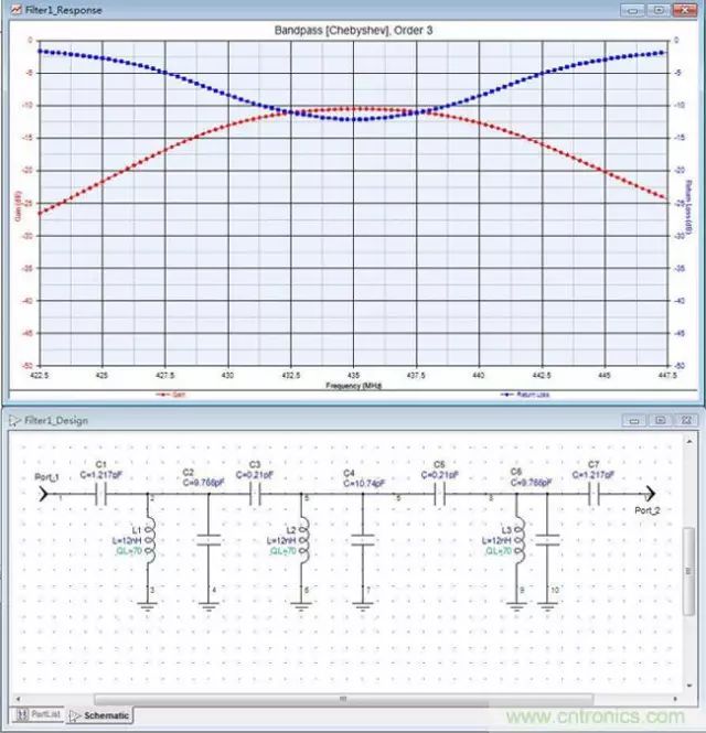
This is a set of Chebyshev band-pass filters with a top capacitor coupling and a center frequency of 435MHz. Due to the use of commercially available chip inductors (which have a Q value of up to 70), the insertion loss is extremely large, reaching -11db, and the other curve is the reflection (which can be converted into standing waves). Therefore, the sensitivity of the receiver is extremely affected, because the sensitivity of the receiver is directly related to the noise figure of the first stage of high amplification, even if the technology is good, such as the noise figure of high amplification can be controlled to 0.5, but the plug loss of the front filter will actually worsen the noise figure by 11db. So it's rare to see one used like this. Look at this picture again:
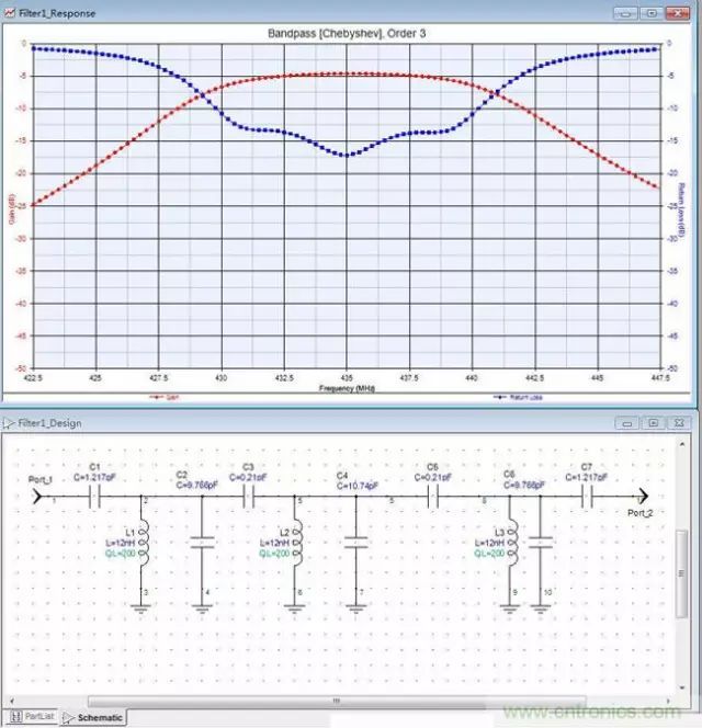
Maintain other parameters, the inductor is replaced by a better hollow coil, although the volume is large, but the insertion loss becomes about -5, which is basically usable, but it is still very difficult to make. Because: The coupling capacitance at the top is only 0.2P, and the capacitance of this capacity is not very easy to buy, so you can only draw the capacitor on the PCB, which brings difficulty to 1 success. Even the 12nH inductor is not very good to wind, and it must be hollow and interwound, and it is not good to master if there is insufficient experience. The inductance is still a bit large, the parameters of those capacitors are more sensitive, and a slight change will affect the performance. So what if you can continue to increase the Q value of the inductor, and there is a way to continue to reduce the coupling capacitance? Then shrink the bandwidth a little bit. The situation would be as follows:
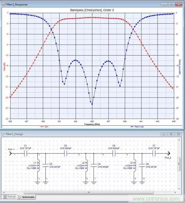
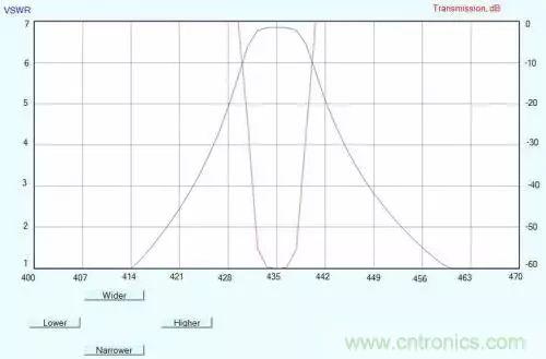
The inductance Q value of this figure suddenly becomes 1600, and the inductance also becomes larger, the graph becomes very beautiful, this filter can ensure the selectivity and sensitivity of the receiver and other indicators, if there is no consideration of energy consumption directly in the back of a piece of IC, suddenly pull the distance up. Better performance, but the size is too large microstrip filter
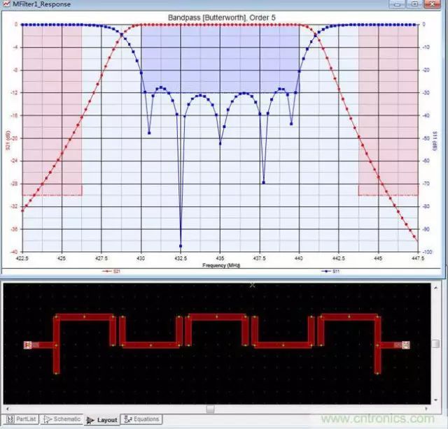
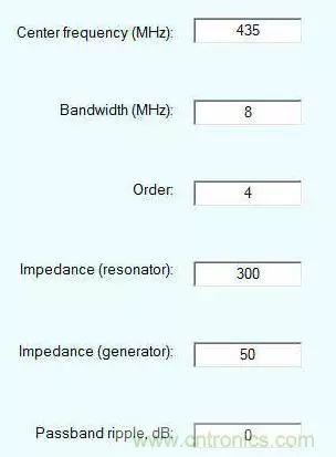
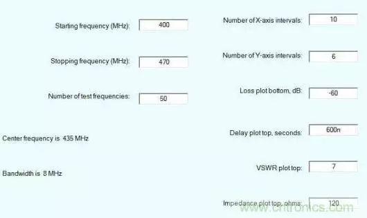
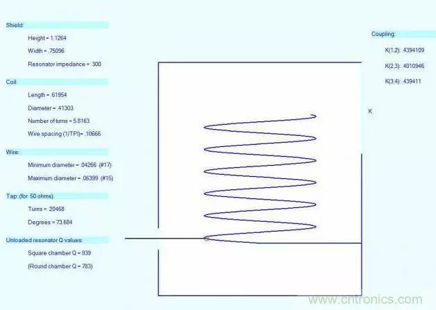
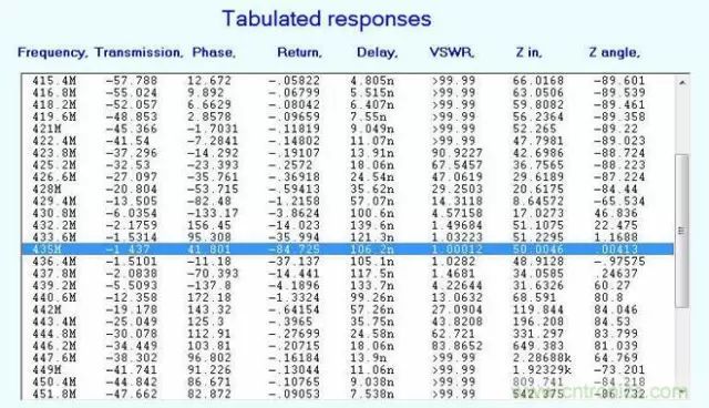
Practical spiral filter design For this spiral filter, the fewer and fewer people will really design in China, and the software can actually be well integrated. First, the previous picture introduces the actual spiral filter for 435MHz mobile devices. In fact, better filters have to be more strictly machined out, we will design high-quality 2-cavity and 4-cavity filters for this testing machine.
Post time: Jul-17-2024


