

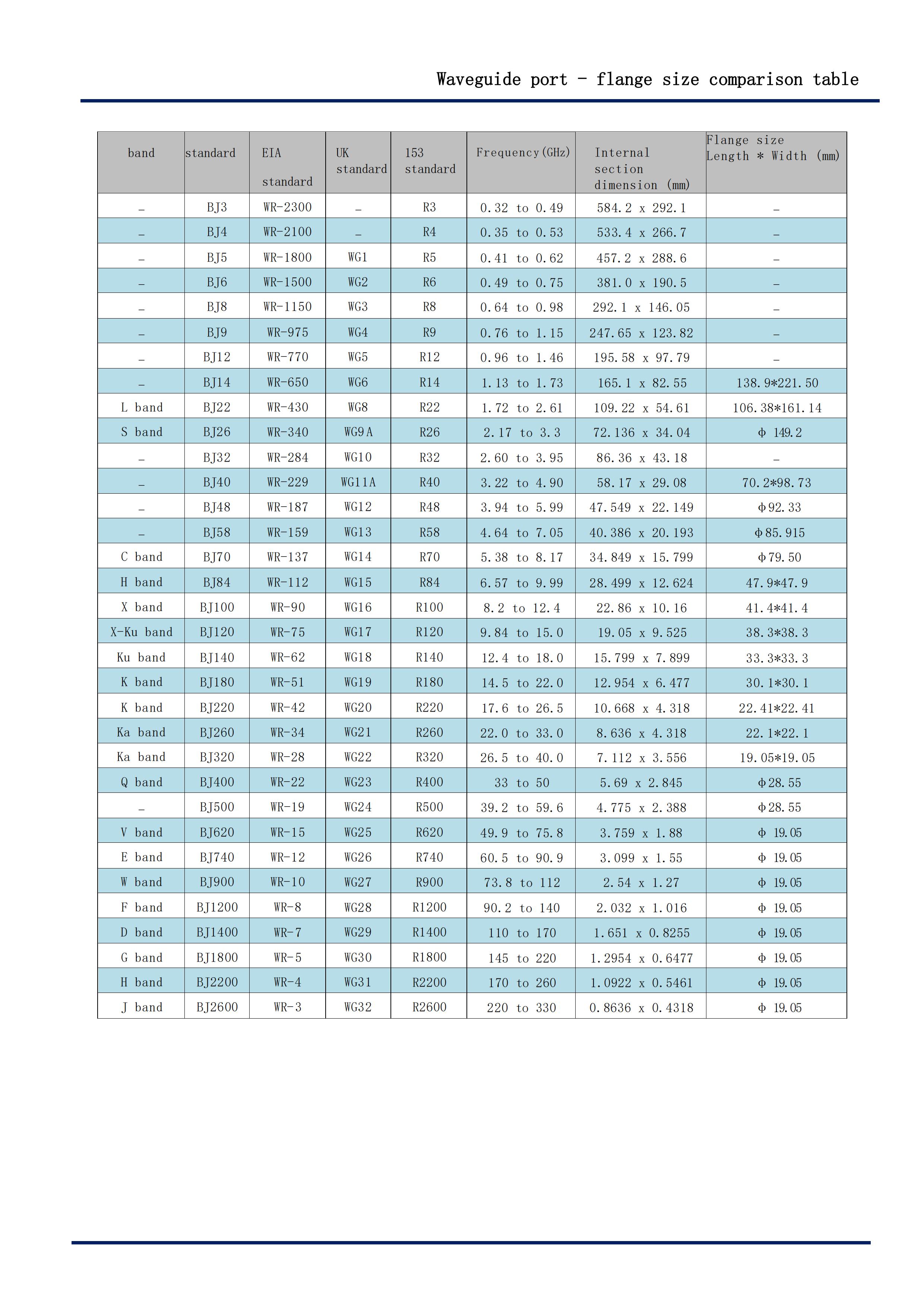
The relationship between **waveguide port dimensions**, **flange sizes**, and **frequency bands** is standardized to ensure mechanical compatibility and optimal RF performance. Below is a simplified comparison table and key principles for common rectangular waveguides and their associated flanges.
---
### **Key Concepts**
1. **Waveguide Designation**:
Waveguides are labeled with "WR" (Waveguide Rectangular) followed by a number (e.g., WR-90). The number approximates the **inner broad-wall dimension** in hundredths of an inch (e.g., WR-90 ≈ 0.90" inner width).
- Example: WR-90 = 0.9" (22.86 mm) inner width.
2. **Flange Types**:
Flanges standardize the connection between waveguides. Common types include:
- **UG/UPC** (MIL-STD): Standardized military flange (e.g., UG-387/UPC).
- **CPR** (Commercial): European standards (e.g., CPR-137).
- **Choke Flanges**: For low-leakage, high-power applications.
- **Cover Flanges**: Simpler, used for vacuum sealing.
3. **Frequency Bands**:
Each waveguide supports a specific frequency range based on its dimensions.
---
### **Waveguide-to-Flange Comparison Table**
| **Waveguide** | **Frequency Range** | **Flange Type** | **Flange Dimensions (Typical)** | **Applications** |
|----------------|---------------------------|-----------------------|-----------------------------------------------|------------------------------|
| **WR-90** | 8.2–12.4 GHz (X-band) | UG-387/UPC (MIL) | Bolt Circle: 1.872" (47.5 mm) | Radar, satellite comms. |
| **WR-112** | 7.05–10 GHz (C-band) | UG-595/UPC | Bolt Circle: 2.400" (61.0 mm) | Radar, telecom |
| **WR-62** | 12.4–18 GHz (Ku-band) | UG-385/UPC | Bolt Circle: 1.250" (31.75 mm) | Satellite, military systems |
| **WR-42** | 18–26.5 GHz (K-band) | UG-383/UPC | Bolt Circle: 0.800" (20.3 mm) | High-frequency radar |
| **WR-28** | 26.5–40 GHz (Ka-band) | UG-599/UPC | Bolt Circle: 0.600" (15.2 mm) | 5G, automotive radar |
| **WR-15** | 50–75 GHz (V-band) | UG-387Mini/UPC | Bolt Circle: 0.400" (10.2 mm) | mmWave, research |
---
### **Flange Dimensions (Typical)**
1. **Bolt Circle Diameter (BCD)**: Diameter of the circle formed by the centers of the mounting bolts.
2. **Hole Spacing**: Distance between bolt holes (e.g., 4-hole or 8-hole patterns).
3. **Waveguide Aperture**: Matches the waveguide’s inner dimensions.
---
### **Key Relationships**
1. **Waveguide Size ↔ Flange Size**:
- Larger waveguides (lower frequencies) use larger flanges (e.g., WR-112 flange > WR-90 flange).
- Smaller waveguides (higher frequencies) use compact flanges (e.g., WR-28, WR-15).
2. **Flange Compatibility**:
- Flanges must match **mechanically** (hole alignment, BCD) and **electrically** (impedance continuity).
- Mixing flange types (e.g., UG-387 with CPR-137) requires adapters.
3. **Standards by Region**:
- **MIL-STD (UG/UPC)**: Common in U.S. defense systems.
- **IEC/CPR**: Common in European commercial systems.
---
### **Example Flange Standards**
| **Flange Type** | **Waveguide Compatibility** | **Key Features** |
|------------------|-----------------------------|-------------------------------------------|
| **UG-387/UPC** | WR-90, WR-62, WR-42 | 4-hole, MIL-STD-392, widely used. |
| **UG-599/UPC** | WR-28, WR-15 | Compact, for mmWave systems. |
| **CPR-137** | WR-112, WR-90 | European standard, 8-hole pattern. |
| **Choke Flange** | All | Grooved design for reduced leakage. |
---
### **Notes**
- Always verify **mechanical drawings** from manufacturers for exact dimensions.
- Mismatched flanges cause **impedance discontinuities**, leading to VSWR degradation.
- For vacuum systems, use **O-ring sealed cover flanges**.
Let me know if you need a specific waveguide-flange combination!
Post time: Feb-22-2025