Products
Normally Open SP11T-12T-18G 18GHz Coaxial Switch
| Leader-mw | Introduction to Normally Open SP11T-12T 18GHz Coaxial Switch |
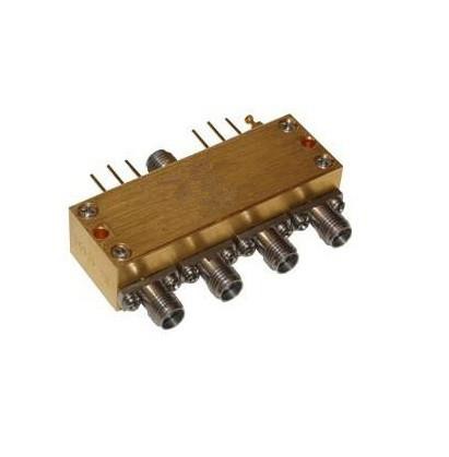
The product in the picture is a coaxial switch with the part number LSP11T - 12T18Ghz. It is normally open and operates from DC to 18GHz.
This coaxial switch has several notable features. It offers low insertion loss, low voltage - standing - wave ratio (VSWR), and high isolation, which are crucial for maintaining signal integrity in RF applications. It is equipped with SMA connectors, which are widely used in microwave and RF systems for their reliable performance.
The switch can be controlled by a selectable TTL driver. The specification table shows that the insertion loss increases slightly as the frequency range goes up from DC to 18GHz. In terms of electrical characteristics, it can operate at different voltages (12V, 24V, 28V) with corresponding coil currents. The environmental specifications indicate a maximum switching time of 15ms and a mechanical life cycle of 2 million cycles, with a storage temperature range of - 55°C to 85°C.
| Leader-mw | specification |
| No. | Frequency(Ghz) | Insertion loss(dB) | Isolation(dB) | VSWR | Powercw(w) |
| 1 |
DC-6 |
0.3 |
70 |
1.3 |
80 |
| 2 |
6-12 |
0.4 |
60 |
1.4 |
60 |
| 3 |
12-18 |
0.5 |
60 |
1.5 |
50 |
| Operating Voltage/Coil Current |
| No. | Operating Voltage(V) |
I2 |
24 |
28 |
|||
| 1 | Coil Current(mA) | Normally open |
300 |
150 |
140 | ||
| No. |
TTL |
TTL Low (v) | TTL high (v) | ||||
| 2 |
0-0.3 |
3-5 |
1.4mA | ||||
| No. | Indicators | Withstand VoltageV (max) | Current capacity mA(max) | Resistance Ω (max) | |||
| 3 | 50 |
100 |
15 | ||||
Remarks:
1.Insertion loss Include Theoretical loss 0.46db 2.Power rating is for load vswr better than 1.20:1
| Leader-mw | Environmental Specifications |
| Switching Sequence: | Break before Make | Switching Time: | 15ms max |
| Storage temperature: | -55℃~85℃ | Mechanical Life Cycles: | 2 million cycles |
| Operating temperature: | -25℃~65℃(Standard)
-45℃ ~85℃(Extended1) -55℃~85℃(Extended2) |
RF Connectors: | SMA Female |
| Weight: | 145g | ||
| Impedance: | 50Ω | Mechanical Shock, Non-Operating: | 50G、1/2 Sine、11 ms |
| Vibration Operating: | 20-2000 Hz、10G RMS | Actuator Terminals: | D-SUB 15/26Pin Male |
| Leader-mw | Mechanical Specifications |
Outline Drawing:
All Dimensions in mm
Outline Tolerances ± 0.5(0.02)
Mounting Holes Tolerances ±0.2(0.008)
All Connectors: SMA-Female


| Leader-mw | Truth Table |
| Normally open Non TTL | |||
| Actuator Terminals | RF Connector | ||
| D-SUB 15Pin Male | |||
| Pin No. | Define | SP11T | SP12T |
| 1 | V1 | RF 1-0 | RF 1-0 |
| 2 | V2 | RF 2-0 | RF 2-0 |
| 3 | V3 | RF 3-0 | RF 3-0 |
| 4 | V4 | RF 4-0 | RF 4-0 |
| 5 | V5 | RF 5-0 | RF 5-0 |
| 6 | V6 | RF 6-0 | RF 6-0 |
| 7 | V7 | RF 7-0 | RF 7-0 |
| 8 | V8 | RF 8-0 | RF 8-0 |
| 9 | V9 | RF 9-0 | RF 9-0 |
| 10 | V10 | RF 10-0 | RF 10-0 |
| 11 | V11 | RF 11-0 | RF 11-0 |
| 12 | V12 | - | RF 12-0 |
| 13 | GND | - | - |
| 14~15 | N/A | - | - |
| Normally open TTL | |||
| Actuator Terminals | RF Connector | ||
| D-SUB 15Pin Male | |||
| Pin No. | Define | SP11T | SP12T |
| 1 | TTL | RF 1-0 | RF 1-0 |
| 2 | TTL | RF 2-0 | RF 2-0 |
| 3 | TTL | RF 3-0 | RF 3-0 |
| 4 | TTL | RF 4-0 | RF 4-0 |
| 5 | TTL | RF 5-0 | RF 5-0 |
| 6 | TTL | RF 6-0 | RF 6-0 |
| 7 | TTL | RF 7-0 | RF 7-0 |
| 8 | TTL | RF 8-0 | RF 8-0 |
| 9 | TTL | RF 9-0 | RF 9-0 |
| 10 | TTL | RF 10-0 | RF 10-0 |
| 11 | TTL | RF 11-0 | RF 11-0 |
| 12 | TTL | - | RF 12-0 |
| 13 | VDC | - | - |
| 14 | GND | - | - |
| 15 | N/A | - | - |
| Leader-mw | Delivery |


