Products
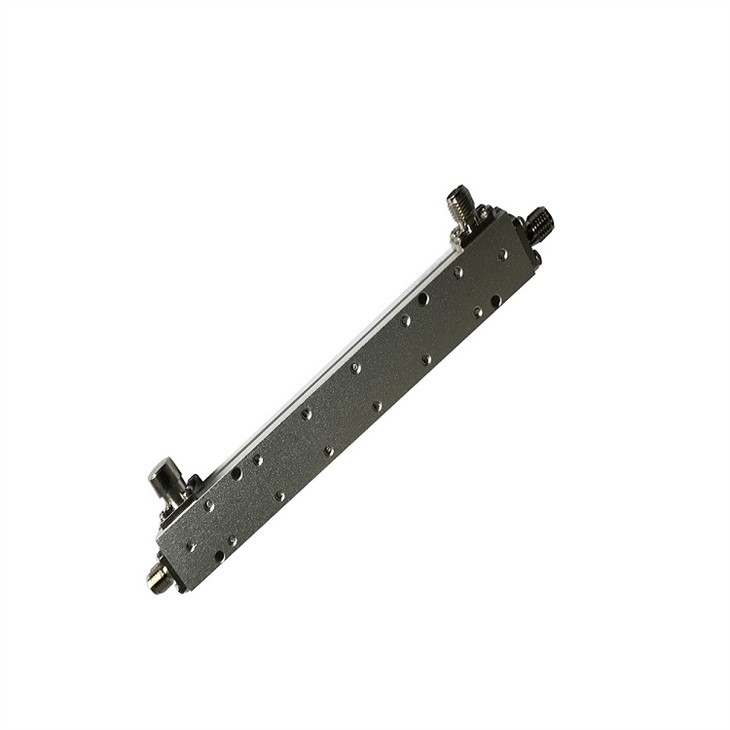
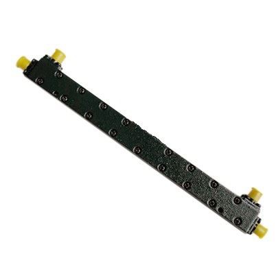
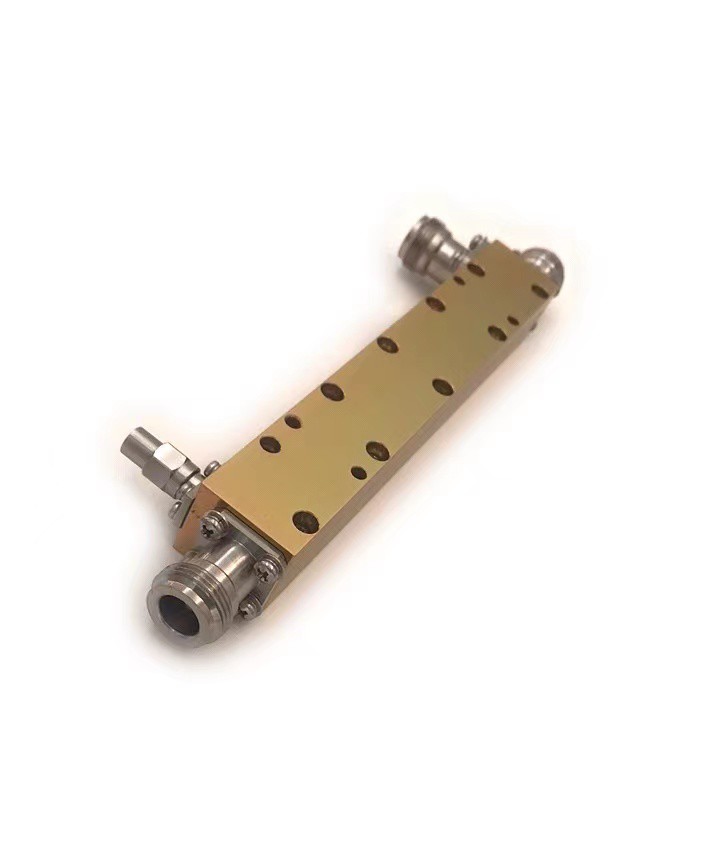
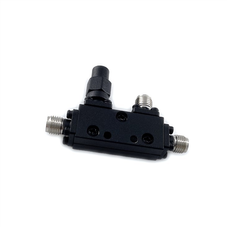
LDC-0.4/6-10S Signal Power Directional RF 10dB Coupler
| Leader-mw | Introduction to Signal Power Directional RF 10dB Coupler |
Signal Power Directional RF 10dB Coupler
**Coupling Factor**: The term "10 dB" refers to the coupling factor, which means that the power at the coupled port (output) is 10 decibels lower than the power at the input port. In terms of power ratio, this corresponds to approximately one-tenth of the input power being directed to the coupled port. For example, if the input signal has a power level of 1 watt, the coupled output will have about 0.1 watt.
**Directionality**: A directional coupler is designed such that it primarily couples power from one direction (typically forward). This means it minimizes the amount of power coupled from the reverse direction, making it suitable for applications where signal flow direction matters.
**Insertion Loss**: While the main purpose of a coupler is to extract power, there is still some loss associated with its presence in the main signal path. A low-quality or poorly designed coupler might introduce significant insertion loss, degrading the overall system performance. However, well-designed couplers like the 10 dB type typically have minimal impact on the main signal, often less than 0.5 dB of additional loss.
**Frequency Range**: The operational frequency range of a coupler is crucial as it determines the range of frequencies over which it can effectively function without significant performance degradation. High-quality couplers are designed to work within specific frequency bands, ensuring consistent coupling characteristics throughout.
**Isolation**: Isolation refers to how well the coupler separates the input and output signals to prevent unwanted interactions. Good isolation ensures that the presence of a load at the coupled port does not affect the signal on the main path.
| Leader-mw | Specification |
| No. | Parameter | Minimum | Typical | Maximum | Units |
| 1 | Frequency range | 0.4 | 6 | GHz | |
| 2 | Nominal Coupling | 10 | dB | ||
| 3 | Coupling Accuracy | ±1 | dB | ||
| 4 | Coupling Sensitivity to Frequency | ±0.5 | ±0.9 | dB | |
| 5 | Insertion Loss | 1.3 | dB | ||
| 6 | Directivity | 20 | 22 | dB | |
| 7 | VSWR | 1.18 | - | ||
| 8 | Power | 20 | W | ||
| 9 | Operating Temperature Range | -45 | +85 | ˚C | |
| 10 | Impedance | - | 50 | - | Ω |
| Leader-mw | Outline drawing |
Outline Drawing:
All Dimensions in mm
All Connectors:SMA-Female


