
Products
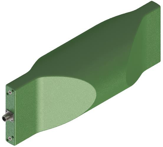
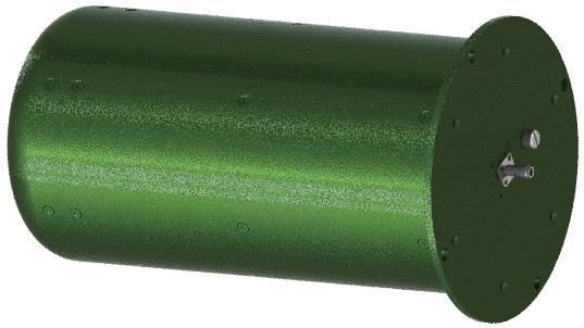
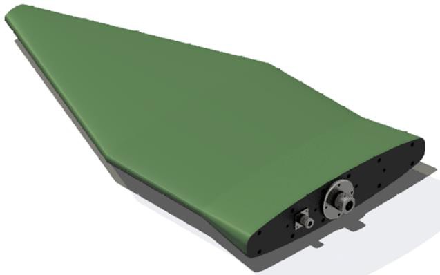
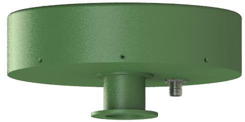
ANT0104 Ultra Wideband Omnidirectional Antenna
| Leader-mw | Introduction to Ultra Wideband Omnidirectional Antenna |
Introducing leader microwave tech.,(leader-mw)new ultra-wideband omnidirectional antenna ANT0104. This powerful antenna is designed to operate over a wide frequency range from 20MHz to 3000MHz, making it suitable for a variety of applications including wireless communications, radar systems and more.
The maximum gain of this antenna is greater than 0dB, and the maximum roundness deviation is ±1.5dB, ensuring reliable and consistent signal transmission. Its performance is further enhanced by a ±1.0dB horizontal radiation pattern, providing excellent coverage in all directions.
ANT0104 has vertical polarization characteristics, making it ideal for applications where vertical transmission is preferred. In addition, the antenna's VSWR ≤2.5:1 and 50 ohm impedance provide optimal impedance matching and minimal signal loss.
Its compact and rugged design makes it suitable for both indoor and outdoor use, and its omnidirectional functionality allows for seamless connectivity in any environment.
Whether you need to increase the signal strength of your wireless network, enhance the performance of your radar system, or simply want to ensure reliable communications over a wide frequency range, the ANT0104 Ultra Wideband Omnidirectional Antenna is the perfect solution.
| Leader-mw | Specification |
ANT0104 20MHz~3000MHz
| Frequency Range: | 20-3000MHz |
| Gain, Typ: | ≥0(TYP.) |
| Max. deviation from circularity | ±1.5dB(TYP.) |
| Horizontal radiation pattern: | ±1.0dB |
| Polarization: | Linear-vertical polarization |
| VSWR: | ≤ 2.5: 1 |
| Impedance: | 50 OHMS |
| Port Connectors: | N-Female |
| Operating Temperature Range: | -40˚C-- +85 ˚C |
| weight | 2kg |
| Surface Color: | Green |
Remarks:
Power rating is for load vswr better than 1.20:1
| Leader-mw | Environmental Specifications |
| Operational Temperature | -30ºC~+60ºC |
| Storage Temperature | -50ºC~+85ºC |
| Vibration | 25gRMS (15 degrees 2KHz) endurance, 1 hour per axis |
| Humidity | 100% RH at 35ºc, 95%RH at 40ºc |
| Shock | 20G for 11msec half sine wave,3 axis both directions |
| Leader-mw | Mechanical Specifications |
| Item | materials | surface |
| Vertebral body cover 1 | 5A06 rust-proof aluminum | Color conductive oxidation |
| Vertebral body cover 2 | 5A06 rust-proof aluminum | Color conductive oxidation |
| antenna vertebral body 1 | 5A06 rust-proof aluminum | Color conductive oxidation |
| antenna vertebral body 2 | 5A06 rust-proof aluminum | Color conductive oxidation |
| chain connected | epoxy glass laminated sheet | |
| Antenna core | Red cooper | passivation |
| Mounting kit 1 | Nylon | |
| Mounting kit 2 | Nylon | |
| outer cover | Honeycomb laminated fiberglass | |
| Rohs | compliant | |
| Weight | 2kg | |
| Packing | Aluminum alloy packing case (customizable) | |
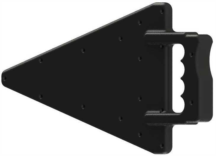
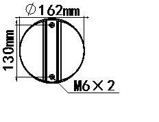
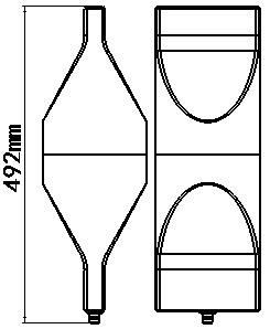
Outline Drawing:
All Dimensions in mm
Outline Tolerances ± 0.5(0.02)
Mounting Holes Tolerances ±0.2(0.008)
All Connectors: SMA-Female
| Leader-mw | Test Data |
| Leader-mw | measurement of antenna |
For the practical measurement of antenna directivity coefficient D, we define it from the dimension of antenna radiation beam range.
Directivity D is the ratio of the maximum radiated power density P(θ,φ) Max to its mean value P(θ,φ)av on a sphere in the far-field region, and is a dimensionless ratio greater than or equal to 1. The calculation formula is as follows:
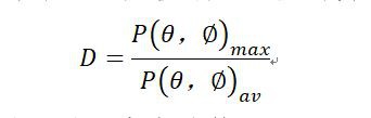
In addition, directivity D can be calculated by the following formula:
D = 4 PI / Ω _A
In practice, the logarithmic calculation of D is often used to represent the directional gain of an antenna:
D = 10 log d
The above directivity D can be interpreted as the ratio of the sphere range (4π rad²) antenna beam range ω _A. For example, if an antenna radiates only to the upper hemispherical space and its beam range is ω _A=2π rad², then its directivity is:
If the logarithm of both sides of the above equation is taken, the antenna's directional gain relative to isotropy can be obtained. It should be noted that this gain can only reflect the antenna's directional pattern radiation, in unit of dBi, since transmission efficiency is not considered as the ideal gain. The calculation results are as follows:
3.01 class: : dBi d = 10 log 2 material
The antenna gain units are dBi and dBd, where:
DBi: is the gain obtained by the antenna radiation relative to the point source, because the point source has ω _A=4π and the directional gain is 0dB;
DBd: is the gain of antenna radiation relative to half-wave dipole antenna;
The conversion formula between dBi and dBd is:
2.15 class: : dBi 0 DBD material